A serial interface RS232 and an IEEE-488-2 connection accommodate
remote control. Apart from that the unit contains a Control Interface with
control lines and relay drivers.
4.2.2 Keyboard / Display
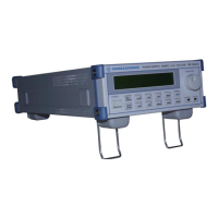
The NGMO control unit consists of the keyboard with rotary transducer
and the detached LC display.
The display is connected to the keyboard via a cable for data and pow-
er supply and another two-pole cable for the LED background illumina-
tion. From the keyboard a common ribbon cable runs to the processor
board. The control processor on the processor board reads out keys
and rotary transducer and presents the up-to-date data on the display.
4.2.3 Analog Boards, CHN ”A“ and ”B“
The two analog boards Channel A and B (NGMO2 only) are electrically
of identical design and offer the following functions beside the typical
functions of a mains supply unit.
• Adjustable output impedance
• fast Push-Pull output stage with reversible bandwidth
• electronic load (current sink)
• high measuring and adjustment accuracy
• quick sampling of output currents and of DVM-voltage with a sam-
pling frequency of up to 100kHz (transient measurement)
• Data storage with 5000 storage locations
• Analysis of recorded current and voltage characteristics
In addition the following safety functions:
• Detection of open sensing lines
• Overvoltage protection (cutoff in case of too high output voltage,
limit adjustable)
• Overcurrent protection (cutoff or limitation to the set current value)
Communication between processor board and one or both analog
boards takes place via a serial interface, which is galvanically separat-
ed by an optical isolator. The analog boards are equipped with a signal
3.00 / 05-2014 4-3

 Loading...