Home
Rohde & Schwarz
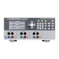
Power Supply
NGMO1
Service Manual
Page 64 (Removing of Keyboard Y202)
Rohde & Schwarz NGMO1 - Removing of Keyboard Y202
76 pages
Manual
To Next Page
To Next Page
To Previous Page
To Previous Page
Loading...
P
o
w
er
S
upp
l
y
NG
M
O
Remo
v
al
and
Inst
a
ll
a
tion
of
A
s
s
e
mbl
i
es
9.1.3
Remov
ing o
f Ke
y
boa
rd Y202
Front Panel
1.
Unscrew
the screw
s on the
f
ront panel
(
1
, 2, 3, 4)
.
2.
Fold the fron
t
panel
careful
ly dow
n.
3.
Pull off plu
gs X101
, X
10
2 and X103 (5
, 6, 7)
.
4.
Unscrew
the screw
s (8, 9, 10
,
11
).
9-4
3.00
/ 05-2014
63
65
Table of Contents
Main Page
Table of Contents
5
User Information
9
NGMO-Versions
9
Ngmo1
9
Ngmo2
9
Purpose of the Handbook
9
Important User Notes
10
Explanation of Symbols
11
Customer Service
13
Service Addresses
13
Technical Support
13
Ordering Spare Parts and Test Equipment
13
Safety
15
General
15
Safety Instructions
15
Unit Description
17
Introduction
17
Fig. 4-1 Power Supply NGMO2, Overall View
17
Function Description
18
Prozessor Board
18
Keyboard / Display
19
Analog Boards, CHN "A" and "B
19
Fig. 4-2 Power Supply NGMO, Function Block Diagram
21
Operation
23
Fig. 5-1 Power Supply NGMO2, Operation Elements
23
Fig. 5-2 Power Supply NGMO2, Connections on Rear Side of Unit
26
Maintenance
29
General
29
Maintenance Intervals
29
Calibration Intervals
29
Cleaning
30
Calibration
31
Calibration Equipment
31
Calibration Adapter
31
Fig. 7-1 Calibration Adapter
31
Calibration Set-Up
32
Fig. 7-2 Power Supply NGMO, Calibration Set-Up
32
Calibration Procedure
33
The Calibration Entry ID Got Lost
40
Repair
43
Function Tests by Using the Service Functions
43
Selecting the Interfaces to be Used
44
Setting the Electronic Serial Number
45
Setting the NGMO Device Name (from Firmware Version 1.10)
46
Communication Test with Analog Boards
47
Commands for Channel: a
47
Commands for Channel: B
47
Display Blank Test
48
Display Unblank Test
49
Keyboard and Knob Test
50
Control I/O Test
52
Fig. 8-1 Test Set-Up for Control I/O Test
52
Inhibit on
54
Fig. 8-3 NGMO Output Plug (2 Pcs.)
54
Switching off Test Functions
56
Error Messages in the Display
57
Checking the Output Voltages
58
Processor Board
58
Analog Boards
59
General Troubleshooting
60
Removal and Installation of Assemblies
61
Removal of Assemblies
62
Removing the Housing
62
Removing of the Analog Board Y101, Y102
63
Analog Board Y101 (Channel A)
63
Analog Board Y102 (Channel B)
63
Removing of Keyboard Y202
64
Removing of Processor Board Y301
65
Removing of Fans A, B
66
Installation of Assemblies
67
Installation of the Analog Boards Y101, Y102
67
Analog Board Y101 (Channel A)
67
Analog Board Y102 (Channel B)
67
Installation of the Keyboard Y202
67
Installation of Processor Board Y301
68
Installation of Fans A, B
68
Assembling the Unit
68
Interfaces
69
Fig. 10-1 Power Supply NGMO2, Non-Standardized Interfaces
69
OUTPUT a / OUTPUT B (Channel a /Channel B)
70
CONTROL I/O (Relay Connector, SUB 15, Male)
71
Bill of Materials
73
Software Update
75
Components List
75
Running the Update
75
Other manuals for Rohde & Schwarz NGMO1
Operating Manual
84 pages
Related product manuals
Rohde & Schwarz Hameg HMP4030
36 pages
Rohde & Schwarz Hameg HMP4040
36 pages
 Loading...