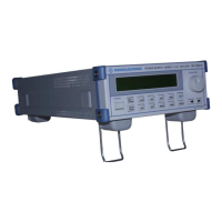
The following bits are set to 0 when:
Turning rotary transducer anti-clockwise Bit 15
Turning rotary transducer clockwise Bit 14
Right hand arrow key Bit 13
Left hand arrow key Bit 12
ENTER key Bit 11
SHIFT key Bit 10
RECALL (9) key Bit 9
OCP (8) key Bit 8
I-SET (7) key Bit 7
OUTP. ON/OFF (6) key Bit 6
MENU (5) key Bit 5
SAVE (4) key Bit 4
OVP (3) key Bit 3
U-SET (2) key Bit 2
CHN/A/B/DVM (1) key Bit 1
LOCAL (0) key Bit 0
If the rotary transducer is turned anti-clockwise and clockwise while all
keys are pressed, the value 0 will finally be returned.
Fault rectification
• If an error occurs:
• Replace the keyboard as described in chapter 9 or
• replace the processor board as described in chapter 9.
3.00 / 05-2014 8-9

 Loading...