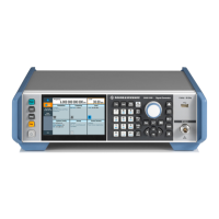
Instrument tour
R&S
®
SMB100B
38Getting Started 1422.1045.02 ─ 06
See also "Annex: Hardware interfaces" and chapter "Network and remote control"
in the user manual.
USB/USB In
●
Female USB (universal serial bus) 2.0 connector of type A (host USB), to con-
nect devices like a keyboard, a mouse, a memory stick, or the R&S NRP-
Z3/Z4 cable for the R&S NRP power sensors
●
Option: R&S SMBB-B86
Female USB 3.0 connector of type Micro-B (USB In), for example, for remote
control.
How to: Chapter 4.8, "Connecting USB devices", on page 25
LAN
RJ-45 connector to connect the R&S SMB100B to a LAN for remote control,
remote operation, and data transfer.
How to: Chapter 4.7, "Connecting to LAN", on page 24
AC power supply connector and switch
Mains power switch for performing the following tasks:
●
Connecting the internal power supply to the power source
●
Disconnecting the internal power supply from the power source
How to: Chapter 4.6, "Connecting to power", on page 24.
S/P Dif
Option: R&S SMBB-B5
BNC input connector for digital stereo signals.
See also "Stereo Modulation" in the user manual.
Stereo L/R
Option: R&S SMBB-B5
BNC input connectors for analog stereo modulation signals. External modulation
sources or the internal LF generator can be used.
See also chapter "Stereo Modulation" in the user manual.
Ref In/Ref Out
Input/output for external reference signal.
BNC connectors for reference signals from 1 MHz to 100 MHz.
SMA connectors for 1 GHz reference signals.
Rear panel tour

 Loading...