7
Rosco Maximizer 2B Asphalt Distributor 7-9
Maintenance
Solenoid Valve Check
The air valves are located in the rear valve compartment.
To check the solenoid valves:
1. Shut Master switch OFF or disconnect the power
wire from the solenoid on the valve.
2. Depress or turn the slotted button on the air valve.
You should hear the valve or air actuator respond.
3. Reset to normal and the valve should return to its
original position.
4. On the 3-Way valve check both top and bottom
solenoid valves.
5. Reconnect the power wire.
Electrical Check
Disconnect power wire and use a digital multimeter to
check the coil resistance. A good coil will have between
30 and 35 ohms resistance.
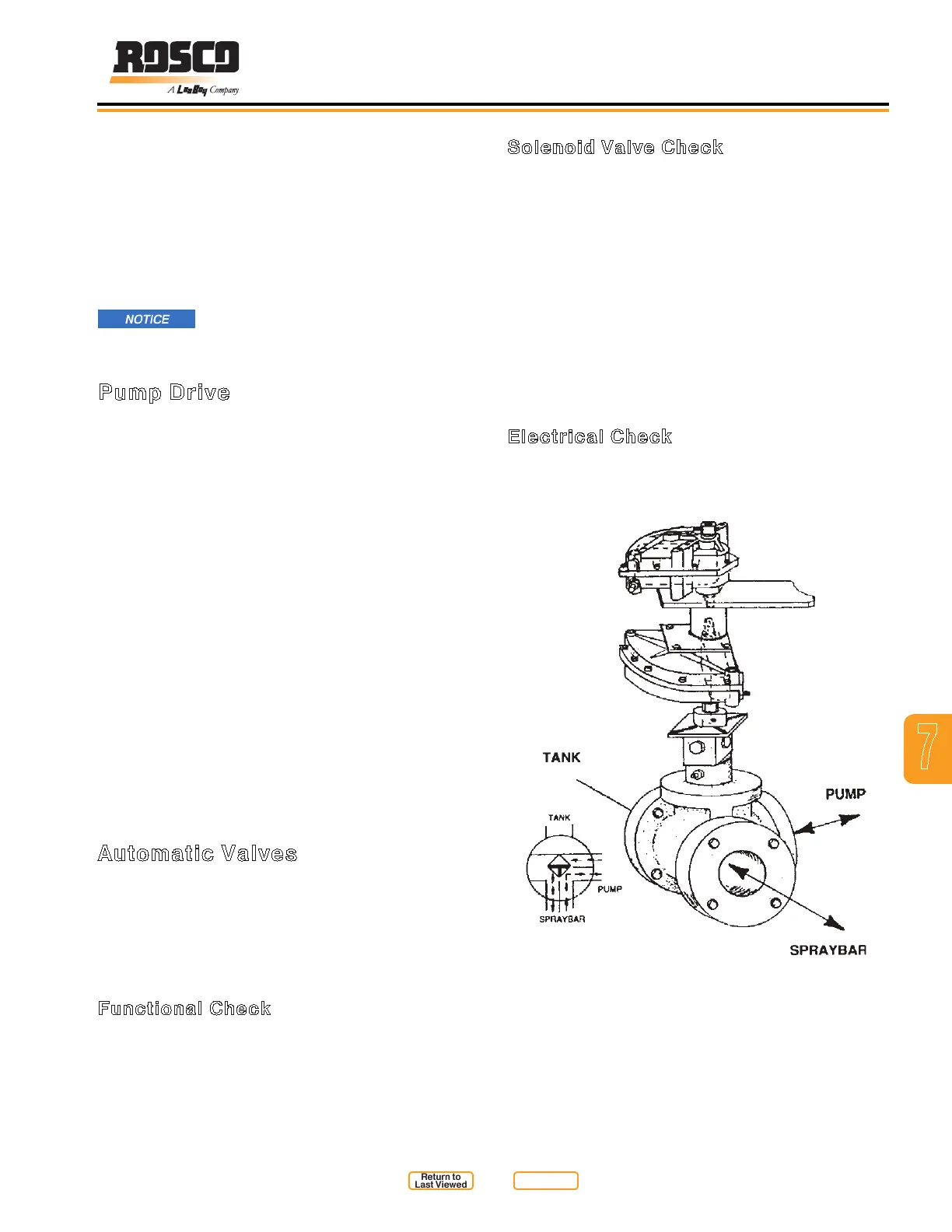
3-Way Valve Position 1
Figure 7-6
Top Solenoid Valve OFF
Bottom Solenoid Valve OFF
1. Visually inspect the screen at the start of each
working day and whenever the cap is removed from
the load line.
2. Remove any objects lodged against the screen. Do
not remove the screen for cleaning.
3. Inspect the screen for damage or holes. If any are
noticed, remove screen from the line and replace
immediately.
Do not operate the machine with a
damaged screen. Objects that enter the system can
damage the pump.
Pump Drive
The asphalt pump is driven by a xed displacement
hydraulic motor through a double chain coupler (Figure
7-1). Inspect the components and maintain the system
in good working order. To inspect the pump drive, follow
this procedure:
1. Stop the engine, place all controls in neutral, set the
park brake and remove ignition key.
2. Allow machine to cool to the touch.
3. Visually check the condition of the coupler on a
bi-weekly basis. If wear can be seen on the rollers
or sprocket teeth, replace the coupler. Be sure
the shafts are aligned and the sprockets securely
fastened to the shaft before resuming operation.
4. A sensor is installed in the hydraulic motor to
measure motor speed. If the sensor malfunctions,
contact an authorized Rosco dealer for assistance.
5. Check the tightness of the hydraulic motor mounting
bolts. Tighten if necessary. Adjust the hydraulic
motor mounts when aligning shaft and chain
coupler.
Automatic Valves
The asphalt ow is controlled by a 2-Way valve, a 3-Way
valve and a Tank Valve. The valves are switched using
electric solenoid valves controlling air ow to the asphalt
valve actuators. Refer to Figure 7-6, Figure 7-7, and
Figure 7-8 to understand the function of the 3-Way
Valve System.
Functional Check
Cycle the Plus One Controller Mode Selection from
one mode to another and watch the valve to see if it
functions correctly (see Table 6-4. Valve Status During
Operational Modes).
Return to
Last Viewed
Return to
Thumb Index