10-64
Rosco Maximizer 2B Asphalt Distributor
Illustrated Parts List (IPL)
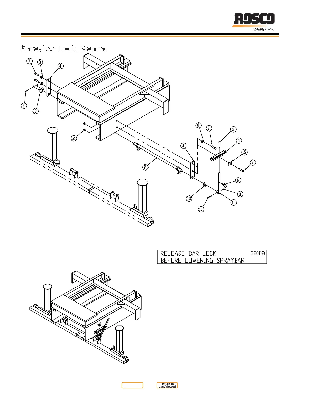
Spraybar Lock, Manual
NOTE:
Item 14, Decal, located on cab Control Box,
above Spraybar Lift switch, and on Rear
Control Box on edge beside Spraybar Lift
switch.
Figure 10-22
Return to
Last Viewed
Return to
Thumb Index