6
Rosco Maximizer 2B Asphalt Distributor 6-9
Operation
Table 6-2. Nozzle Size to Application Rate
NOZZLE
SIZE
APPLICATION RATE (GPM)
00
Extremely Light (1.5)
0 Light (4.0)
1 General (5.0)
1.5 Intermediate w/ certain emulsions (6.0)
2 Heavy (10.0)
3 Extra Heavy (15.0)
Burners & Torch
Operation
Diesel Burners
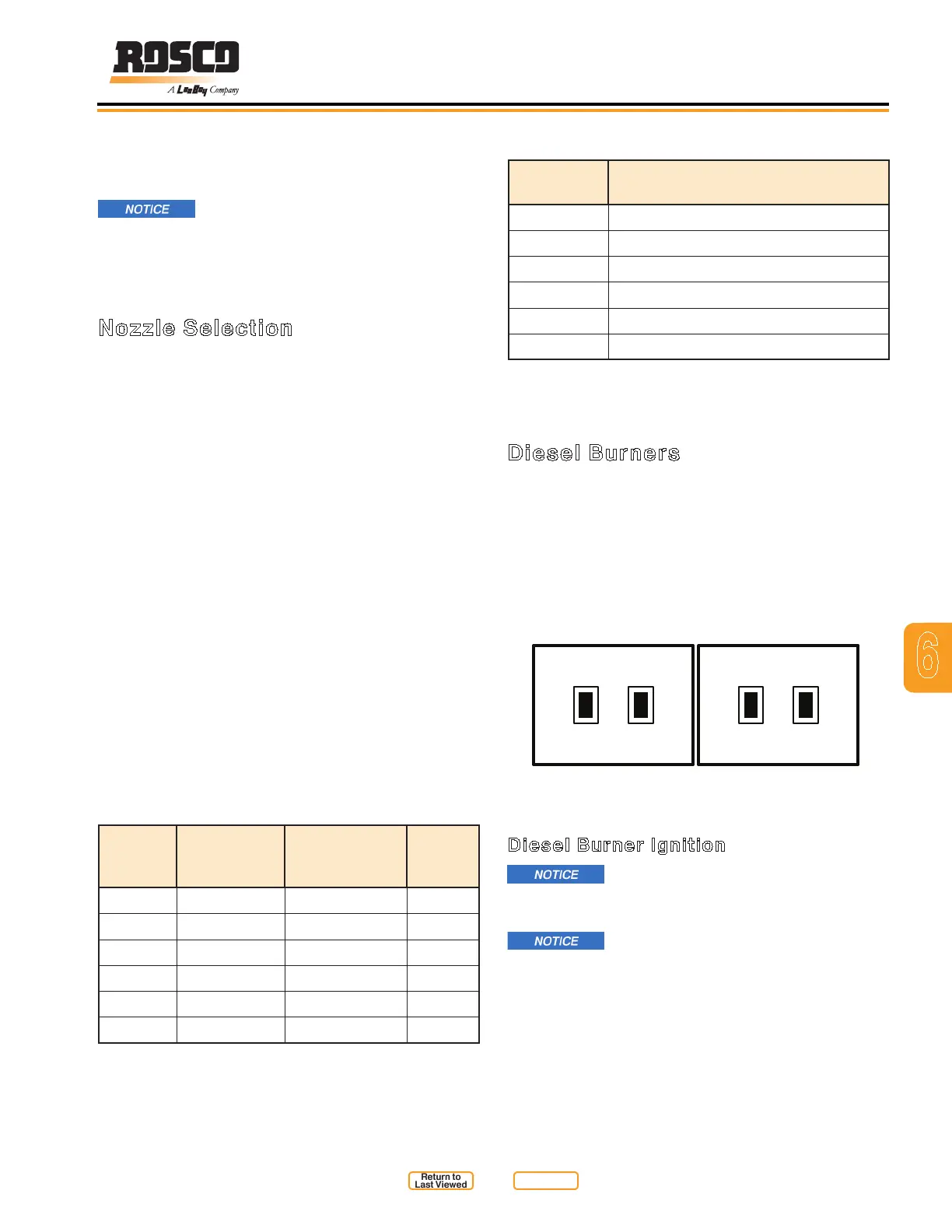
Control switches for the electronic ignited diesel
burners are mounted on the driver side rear fender,
(Figure 6-6).
1. Fuel Switch: Activates burner fuel solenoid and
ignites burner. Turn off to extinguish burner.
2. Blower Switch: Activates blower and fuel pump.
UPPER BURNER
FUEL BLOWER
READ SAFETY INSTRUCTIONS
PRIOR TO USE
READ SAFETY INSTRUCTIONS
PRIOR TO USE
FUEL BLOWER
LOWER BURNER
Fender Diesel Burner Switches
Figure 6-6
Diesel Burner Ignition
Before heating asphalt material, refer
to Systems Overview, Burner System, earlier in this
section for further information and precautions.
Run the burners for short periods
of time (15 minutes ON, 15 minutes OFF) to allow
the heat to dissipate through the material. This will
prevent damage to the ue liner.
NOTE: The valve on top of each cylinder must be placed
in the proper direction for correct function of the
spray system.
Always check the function of the valve
after servicing and before starting a job. Be sure
there is a proper connection and no leakage.
For a further breakdown of the spraybar valve assembly,
(see Illustrated Parts List (IPL) in Section 10).
Nozzle Selection
The correct nozzle selection depends on:
1. the application rate setting
2. the truck speed
3. the type of material being sprayed.
The standard Rosco nozzle size is a NO. 1. However,
other factors will determine efciency and the quality
of the spray pattern. Exceeding nozzle maximum ow
rate may cause fogging and inconsistent application
rates. Using a nozzle that is too large will cause a poor
spray pattern, (Table 6-1. Nozzle Size to Flow Rate and
Table 6-2. Nozzle Size to Application Rate).
The recommended nozzle angle is 20° and is set
to that specication at the factory. After changing
nozzles, or when adjustments need to be made, use
the Nozzle Alignment Wrench (Leeboy #8695) and the
Valve Alignment Tool (Leeboy #18981) for accurate
positioning. Tools are provided with each unit, (Figure
6-4).
NOTE: For additional information about nozzle selection
and adjustment, see applicable troubleshooting
topics (see Maintenance in Section 7).
Table 6-1. Nozzle Size to Flow Rate
NOZZLE
SIZE
RECOMM-
ENDED
FLOW - GPM
APPLICATION
RATE - GAL /
SQ. YD.
ROSCO
PN
00 1.2 .03 - .08 35565
0
3.0 .05 - .20 32917
1
4.0 .10 - .30 32918
1.5 6.0 .15 - .40 36299
2
8.5 .25 - .55 32919
3
13.5 .35 - 1.00 32920
Return to
Last Viewed
Return to
Thumb Index