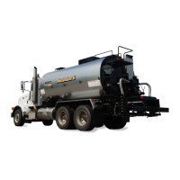
Rosco Maximizer 2B Asphalt Distributor ix
Table Of Contents
Electrical Schematic - Control, Front Machine 1 of 1 . . . . . . . . . . . . . 9-19
Electrical Schematic - Control, Rear Machine 1 of 1 . . . . . . . . . . . . . 9-21
Electrical Schematic - Control, LH Spraybar 1 of 1 . . . . . . . . . . . . .9-23
Electrical Schematic - Control, RH Spraybar 1 of 1 . . . . . . . . . . . . .9-25
Electrical Schematic - Can Bus Kit 1 of 4 . . . . . . . . . . . . . . . . . . 9-27
Electrical Schematic - Can Bus Kit 2 of 4 . . . . . . . . . . . . . . . . . . 9-29
Electrical Schematic - Can Bus Kit 3 of 4 . . . . . . . . . . . . . . . . . . 9-31
Electrical Schematic - Can Bus Kit 4 of 4 . . . . . . . . . . . . . . . . . . 9-33
Illustrated Parts List (IPL) . . . . . . . . . . . . . . . . . . . . . . . . . .10-1
Platform Installation, w/o Handrail
. . . . . . . . . . . . . . . . . . 10-4
Rear Platform and Piping Assembly
. . . . . . . . . . . . . . . . . 10-6
Rear Platform and Piping Assembly (continued) . . . . . . . . . . . 10-8
Asphalt Pump . . . . . . . . . . . . . . . . . . . . . . . . . . . . 10-10
Asphalt Pump Relief Valve . . . . . . . . . . . . . . . . . . . . . . 10-12
Transfer Line, Ground Level . . . . . . . . . . . . . . . . . . . . . 10-14
Automatic Valve, Cab Control . . . . . . . . . . . . . . . . . . . .10-16
Tank Valve Assembly . . . . . . . . . . . . . . . . . . . . . . . .10-18
Flex Hose Assembly . . . . . . . . . . . . . . . . . . . . . . . . .10-20
Handspray Wand Assembly . . . . . . . . . . . . . . . . . . . . .10-22
Hydraulic, Front Live . . . . . . . . . . . . . . . . . . . . . . . . .10-26
Hydraulic, PTO . . . . . . . . . . . . . . . . . . . . . . . . . . .10-34
Spraybar Support Assembly . . . . . . . . . . . . . . . . . . . . .10-40
Solenoid Control Valve (Sheet 1 Of 2) . . . . . . . . . . . . . . . .10-42
Solenoid Control Valve (Sheet 2 Of 2) . . . . . . . . . . . . . . . .10-44
Hydraulic Reservoir . . . . . . . . . . . . . . . . . . . . . . . . .10-46
Drive Shaft Group . . . . . . . . . . . . . . . . . . . . . . . . . .10-48
Control Box, Plus One, In-Cab Control Box . . . . . . . . . . . . . .10-50
Radar Horn (Option) Ground Speed Sensor . . . . . . . . . . . . .10-52
Rear Control Box Assembly . . . . . . . . . . . . . . . . . . . . .10-54
Spraybar Assembly, 12 Foot . . . . . . . . . . . . . . . . . . . . .10-56
Arm Wldmt, Upper Rh . . . . . . . . . . . . . . . . . . . . . . . .10-58
Air Controls, 12 Ft Spraybar, 1 Ft Control (Sheet 1 Of 2) . . . . . . . 10-60
Spraybar Lock, Manual . . . . . . . . . . . . . . . . . . . . . . . .10-64
Valve Box, Sub Assembly, 1 Ft, With Wingfold . . . . . . . . . . . . 10-66
Valve Box, Sub Assembly, 1 Ft, With Wingfold . . . . . . . . . . . . 10-68
Diesel Burner, Double Flue, No Outre . . . . . . . . . . . . . . . .10-70
Return to
Last Viewed
Return to
Thumb Index