Reference Manual
00809-0100-4841, Rev. AA
May 2007
2-5
Rosemount 3490 Series
Display The LCD display shows both text and graphical information. After the
power-up and self-checks are completed, the Primary Display is presented.
The default display typically features a digital clock, measured variable with
display units, and status icons.
There are some display differences between the models:
• On models 3491 and 3492, a bar graph represents the 4-20mA output
signal. (Model 3493 display can be programmed to show the bar graph.)
• On model 3492, there are extra graphics relating to having two
transmitters connected to the control unit.
• On model 3493, there are two totalisers displayed; one above and one
below the measured variable.
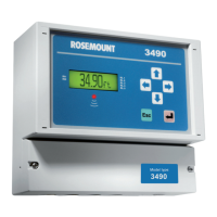
Figure 2-3.
Typical display of model 3491
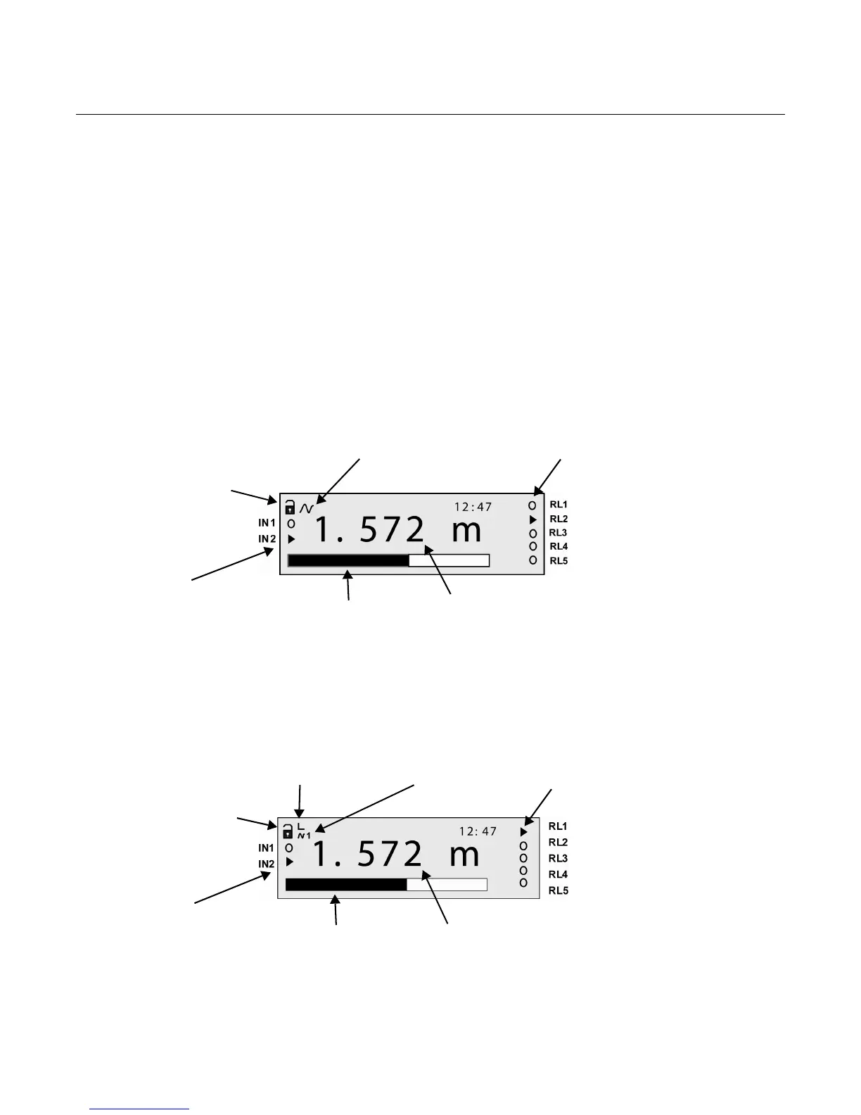
Figure 2-4.
Typical display of model 3492
HART Transmitter
communicating
(Absent if idle)
Measured PV
(Primary Value)
Bar graph of
4-20mA output
Off-line/on-line status.
(Locked padlock = on-line)
Relay (RL) status.
(o = de-energized,
= energized)
Digital input status
(o = de-energized,
= energized)
Transmitter allocated
Left vertical bar = Tx1
Right vertical bar = Tx2
Transmitter
communicating
(1=Tx1, 2=Tx2)
Measured PV
(Primary Value)
Bar graph of
4-20mA output
Off-line/on-line status.
(Locked padlock = on-line)
Relay (RL) status.
(o = de-energized,
= energized)
Digital input status
(o = de-energized,
= energized)