Reference Manual
00809-0100-4841, Rev. AA
May 2007
Rosemount 3490 Series
3-10
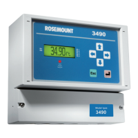
Figure 3-5.
self-powered transmitter
connections to 3490 Series
Control Unit
NOTE:
The plug/socket connectors are polarized to prevent inter-changeability and
incorrect connection
Connecting HART
Transmitters to 3492
Model 3492 of the Rosemount 3490 Series takes the input from two HART
transmitters and will perform various calculations to create the sum,
difference, or product of the two inputs.
NOTE
The transmitters must be HART compatible for the 3492 to operate correctly.
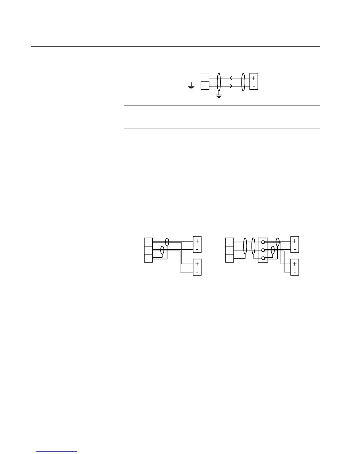
Connection of the transmitters to the 3492 may be by cabling both transmitter
cables into the 3492 (Figure 3-6), or may be on a single cable with the two
transmitters connected to this cable via a suitable junction box (Figure 3-6).
Figure 3-6. Connecting HART
transmitters to 3492
For correct operation, each transmitter must be changed to “multi-drop” mode
so that they can communicate with the 3492 through a common connection.
Each transmitter must therefore have it’s poll address changed from the
factory default address of “0” to a unique address.
The 3492 is used to achieve this address change, but requires the
transmitters be connected in a specific sequence as detailed here:
a) With the power supply turned off, connect the first transmitter to
terminals 1-3 on the 3492.
b) Check that the power-selector-switch is set for the correct voltage
(115 or 230V ac) on the mains unit, and then turn the power on.
c) The 3492 will detect the transmitter and automatically change the poll
address of the transmitter from “0” to “1”. This transmitter will also be
automatically allocated to Channel 1 of the 3492.
Note that the 3492 may also offer the user the opportunity to set the
Bottom Reference of the transmitter at this point, which may be done or
ignored by pressing the ESC button.
1
2
3
24V
Iin
(Control Unit)
(Transmitter)
1
2
3
Tx1
Tx2
1
2
3
Tx1
Tx2
Junction
Box