Reference Manual
00809-0100-4841, Rev. AA
May 2007
Rosemount 3490 Series
3-4
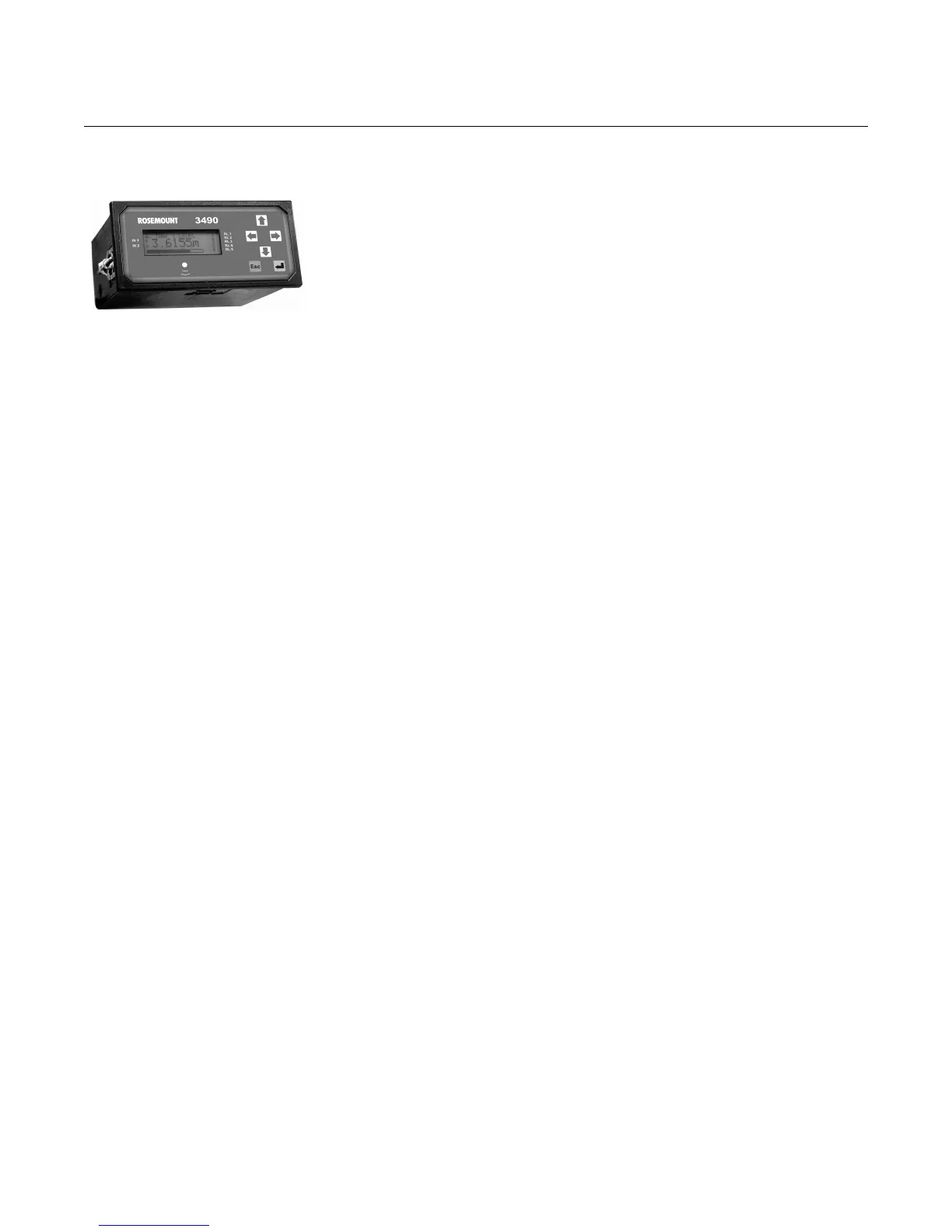
Mounting Panel Models Guidelines:
• This housing is rated IP40 and is designed for panel mounting in a
weatherproof environment. An optional fascia overlay hood is available
which improves the IP rating to IP65.
• Do not mount the Control Unit on a structure that is subject to vibration, or
in a position where damage may be caused by impact, thermal stress, or
liquid ingress.
• A rack mounting kit is available that allows mounting of the unit in a
standard 19-inch rack. Up to two units can be mounted in one rack; each
unit requires a rack mounting kit.
Where three of more units are fitted in the same cabinet or panel, ensure
that there is adequate air circulation to aid cooling. It is recommended that
an air circulation fan be fitted.
• The unit requires at least 165mm clearance behind the mounting panel to
avoid cable fouling.
• Once mounted, all wiring is made at the rear of the unit using the two part
terminal blocks provided. (On model 3493, a pre-wired data download
socket suitable for front panel mounting is provided with the unit.)
• Mount the control unit on a panel with thickness 1.5mm to 10mm,
ensuring the panel is strong enough to support the 1.2kg weight of the
control unit.
• Ensure there is enough clearance behind the chosen position in the panel
(165mm minimum), cut a slot 138mm long by 68mm high (i.e. landscape
or horizontal slot) in the panel and remove any rough edges.
Procedure:
a) Unpack the two screw clips provided.
b) Identify the moulded lugs in the moulded recesses on each side of the
control unit. (Ignore the recesses on the top and bottom of the control
unit).
c) Holding the screwdriver-slot-end of the threaded spindle of a screw
clamp and looking at the rear of the control unit, locate the screw clamp
frame on the side of the control unit. See how the 4 steel lugs of the
screw clamp frame locate on the moulded lugs of the control unit.
d) Now gently pull the screw clamp such that the lugs engage with each
other (see Figure 3-1 on page 3-5).
e) Remove the screw clamps from both the screw clamp frames.
f) Slide the control unit into the panel, ensuring that the panel seal provided
is in place behind the front panel bezel.
g) Re-fit the screw clamps, one on each side, and tighten with a screwdriver
to clamp the control unit against the panel.
h) For electrical connections, see.“Electrical connections on Panel Mount
Model“ on page 3-8.