Reference Manual
00809-0100-4841, Rev. AA
May 2007
Rosemount 3490 Series
3-8
Electrical connections
on Panel Mount Model
All connections are made to the rear of the control unit using the two part
terminal connectors provided.
NOTE
It is the responsibility of the installer to:
• Refer to safety data and electrical specifications in Appendix A.
• Refer to Product Certifications and Control Drawings in Appendix B
• Observe all local regulations and approval requirements.
• Check and obtain any hazardous area work permits required before
applying power to the control unit.
• Ensure the wiring is suitable for the load current.
• Ensure wiring insulation is suitable for the voltage, temperature, and
environment of the installation.
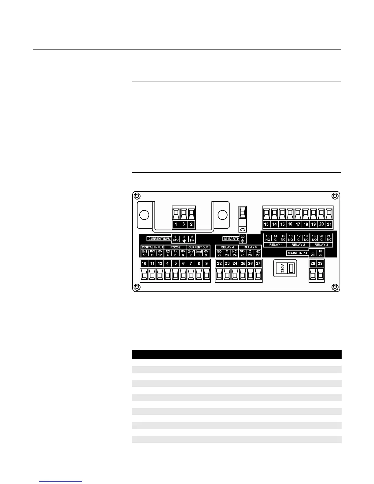
Figure 3-3.
Connection terminal layout
(mains powered panel unit)
(DC powered version has slightly different layout i.e. terminals 31 and 32 replace terminals 28 and 29).
Transmitter connections are on the left side of the terminals enclosure.
The Intrinsically Safe Earth (terminal 30) must be connected to a
High Integrity Earth if the transmitter connected to terminals 1 and 2 is sited in
a hazardous area.
Table 3-2. Connection
descriptions for panel mount unit
Terminal Function Layout
1 Loop supply 24V
2 Current input Iin
3 Cable screen Earth (Earth symbol)
4-6 RS232 RX-TX-0V
7-9 Current output 24V-Iout-0V
10-12 Digital input 1 and 2 IN1-IN2-0V
13-15 Relay 1 NO-COM-NC
16-18 Relay 2 NO-COM-NC
19-21 Relay 3 NO-COM-NC
22-24 Relay 4 NO-COM-NC
25-27 Relay 5 NO-COM-NC
28-29
(1)
Mains input L-N