Reference Manual
00809-0100-4841, Rev. AA
May 2007
Rosemount 3490 Series
3-12
Relay Connections The 5 voltage-free contact relays are grouped in the following configuration:
Table 3-3.
Relay configuration groups
The relay NO-COM-NC labels represent the relay terminals in the
de-energised state.
NOTE:
Whilst each relay is individually double-insulated, their arrangement is such
that the insulation between relays in the same group is standard or ‘basic’
insulation.
NOTE:
Care must be taken in order to avoid the risk of electric shock. It is
allowed to use relays in the same group to control circuits with both mains and
dc, or low voltage circuits.
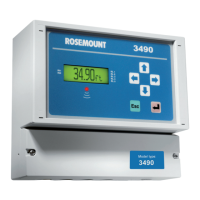
Current Output
Connections
The Current Output may be connected in internally-powered mode or
loop-powered mode, as shown in Figure 3-7.
In loop-powered mode, an external power source is required. A minimum of
2.5V is required across terminals 7 and 8 for correct operation. The external
voltage must not be more than 30V dc.
Figure 3-7.
Alternative Current Output
configurations
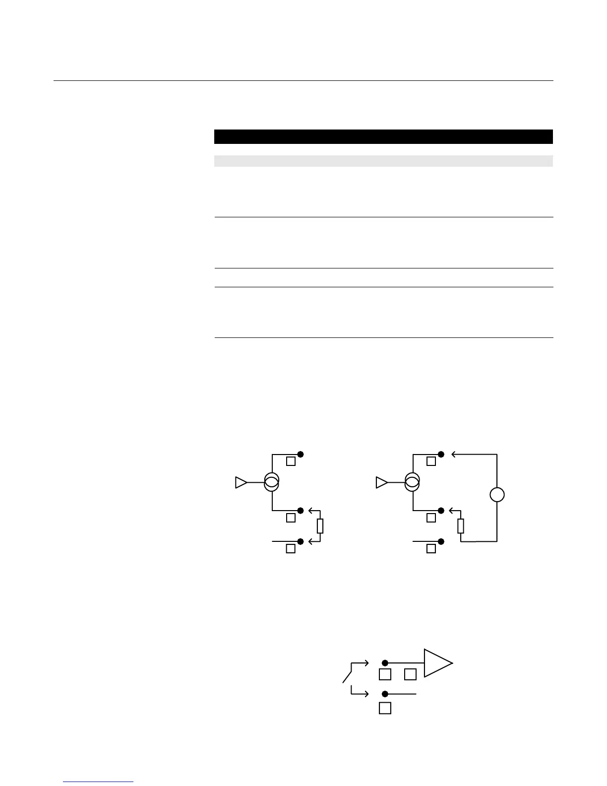
Digital Control Voltage
free Contact Inputs
There are 2 trigger inputs, IN1 and IN2. The digital trigger input is connected
as shown in Figure 3-8.
Figure 3-8. Connections for
external trigger input
3490 Series Control Unit (Wall Mount) 3490 Series Control Unit (Panel Mount)
Relay 1 and 2 : Group 1 Relay 1, 2 and 3 : Group 1
Relay 3 and 4 : Group 2 Relay 4 and 5 : Group 2
Relay 5 - Group 3
7
8
9
0V
Io
24V
Load
+
-
7
8
9
0V
Io
24V
Load
External
Supply
+
+
-
-
Internally Powered Loop Powered
IN
External
Contact
Closure
0V
or10 11
12