6.3 Hydraulic connections
6.3.1 Water circuit connection
When you are preparing to implement the hydraulic circuit, you must comply with the following
requirements and adhere to national or local legislation.
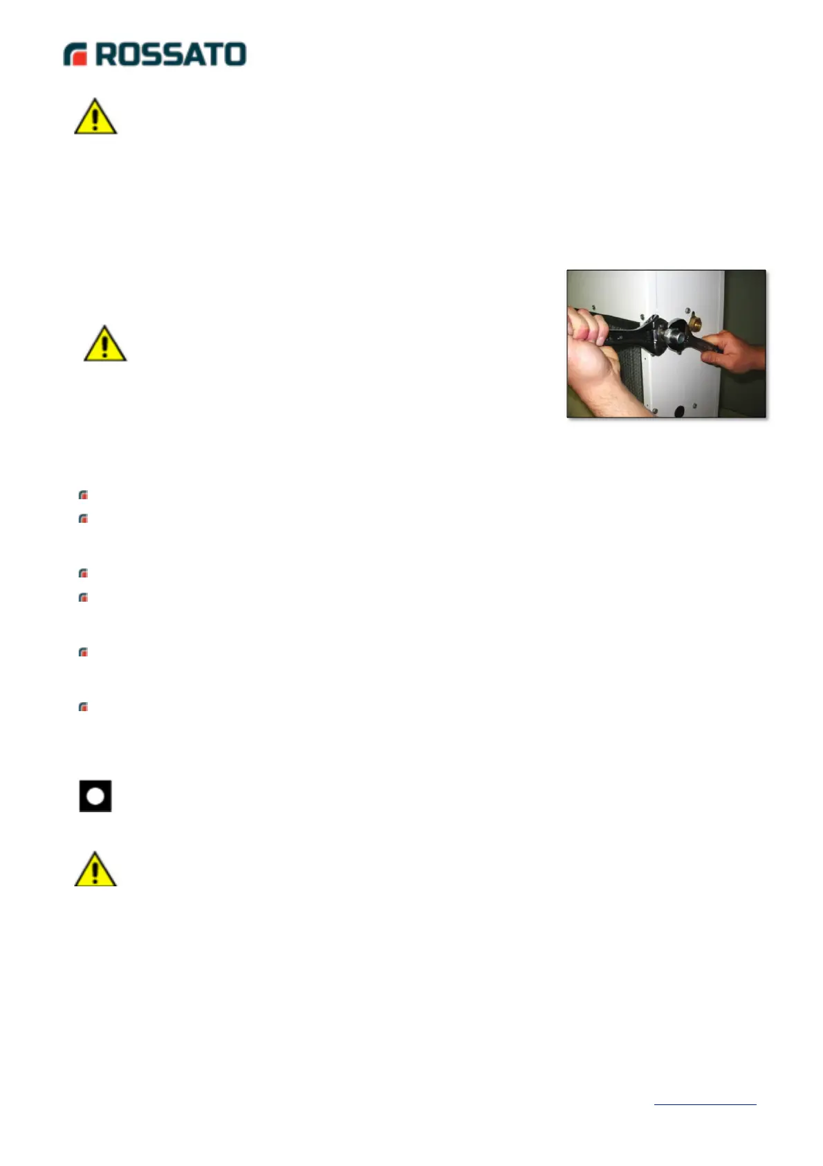
Connect the tubes with flexible joints in order to prevent the transmission of vibrations and
compensate for thermal dilatations.
It is recommended to install the following components on the tubes:
temperature and pressure indicators for unit maintenance and control. Pressure control
allows assessing the proper functionality of the expansion tank and shows any water
leakage of the system in advance;
shut-off valves to isolate the unit from the hydraulic circuit, in case of maintenance work;
metal net-type filter (inlet pipe) with meshes not wider than 1 mm, in order to protect the
exchanger from slag or impurities present in the piping. This requirement is necessary
especially for the first commissioning;
purge valves, to be placed at the higher parts of the hydraulic circuit, to allow purging.
There are manual purge valves installed on the inner machine tubes: this operation must
be performed with the unit not under tension;
drain valve and, where necessary, drain tank to allow the emptying of the system for
maintenance operations or seasonal stand-by.
The size and position of the hydraulic connections are shown in the overall designs.
6.3.2 Condensation drain connection
Perform the connection using a flexible rubber tube with a 16 mm internal diameter. A siphon
must be made on the drain tube, having a lathe at least equal to intake prevalence of the fan, as
shown below:
CAUTION:
It is very important that the water inlet takes place at the connection marked by the indication
"Water Inlet". Otherwise, the circling in counter-current will not be implemented with risk of
malfunctioning, block or breakage of the unit.