DK00026.fm
REPAIR MANUAL
BRP-Powertrain
Effectivity: 125 MAX/125 Junior MAX/125 Mini
MAX/125 Micro MAX
Edition 2 / Rev. 0
Chapter 4
Page 24
December 01/2010
Exhaust valve,
gasket, valve rod
housing
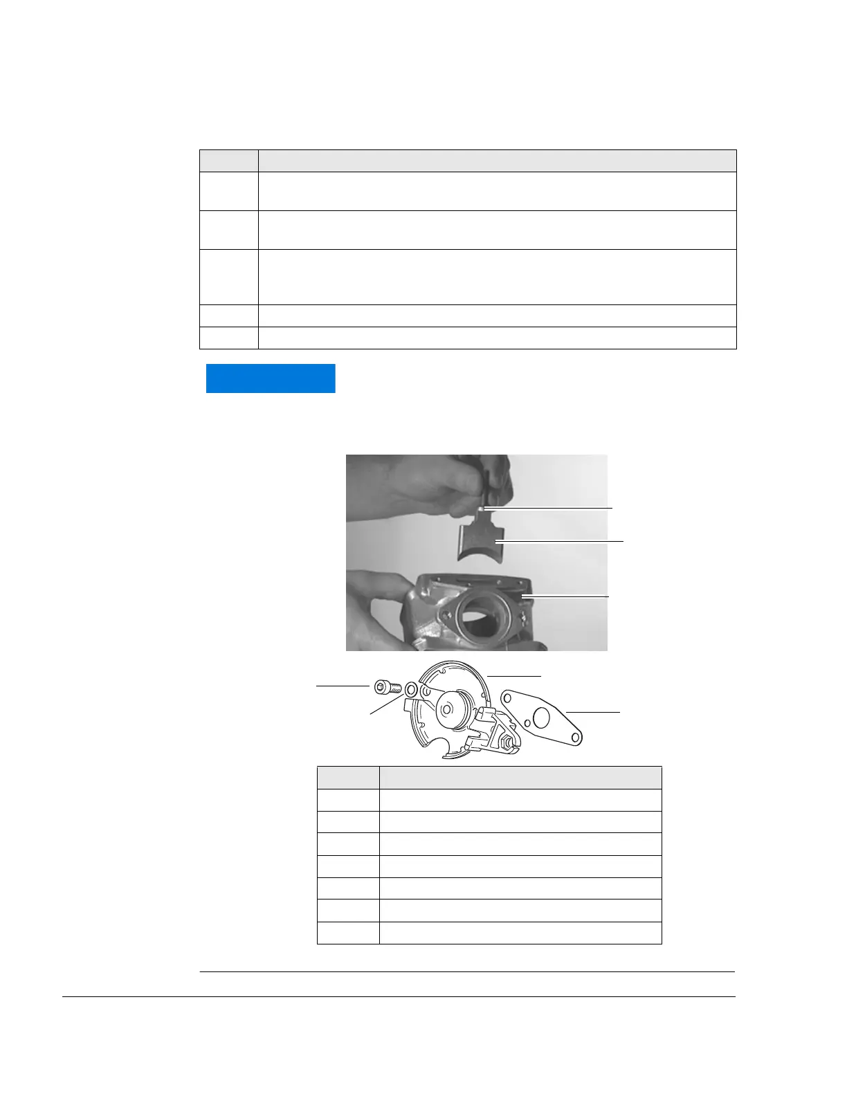
See Figure 17.
Graphic Installation direction of exhaust valve
Figure 17
K00048, K00157
Step Procedure
4 Insert exhaust valve into the slot in the cylinder (1). Pay attention on the instal-
lation direction!
5 Position the gasket (4), making sure that the impulse bore on the cylinder is
not covered. Note the installation direction!
6 Insert the valve rod housing (5) with the cutout facing to the exhaust socket.
Screw in 2 cyl. screws M6x16 (6) and spring washers (7) onto the cylinder (2)
and tighten.
7 Check the movement of the exhaust valve.
8 Tighten cyl. screws. Tightening torque 10 Nm (90 in.lb).
If the exhaust valve does not move freely or is jammed,
the valve rod housing must be removed and rein-
stalled.
Part Function
1 Cylinder
2 Exhaust valve
3O-ring
4 Gasket
5 Valve rod housing
6 Cyl. screws M6x16
7 Spring washers