7.7) Exhaust system
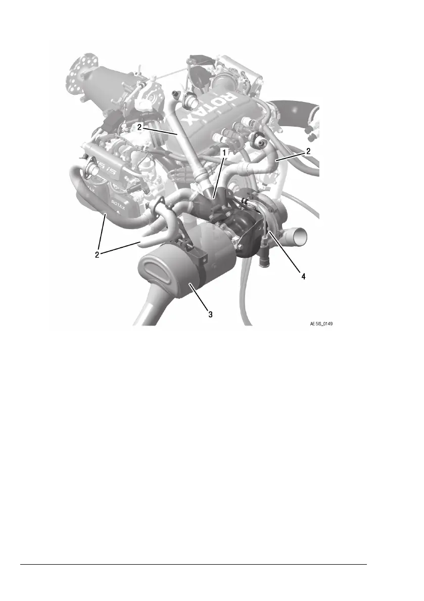
Figure 12: Turbocharger/Exhaust system
1 Exhaust manifold 2
Exhaust pipes
3 Muffler 4
Turbocharger
Exhaust flow
The Exhaust gases are pushed out of the cylinders thru the ex-
haust pipes and are brought together in the exhaust manifold.
From there the exhaust gas pass the turbine side of the turbo-
charger (depending on the waste gate position). From there the
exhaust gases leave the engine thru the muffler.
Exhaust Gas Tem-
perature Sensors
(EGT)
The sensors for reading the exhaust gas temperature are lo-
cated the exhaust pipes near the cylinder outlet.
Page 7-16
December 01 2017
BRP-Rotax Effectivity: 915 i A Series
Edition 0 / Rev. 0

 Loading...


