4 x Installation
FA ROTEX Solaris RPS4 - 06/2015
11
4.2.2 Installation FlowSensor, FlowGuard (optional)
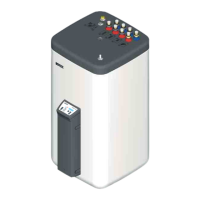
FlowSensor
The FlowSensor FLS 20 (fig. 4-17) is a measuring device that
simultaneously determines the flow rate in the solar panel and the
flow temperature. The measuring ranges are 0...20 l/min (flow
quantity) and 0...120 °C (inflow temperature). The measured
values are displayed on the Solaris R4 controller. By speed
regulation of the solar operating pump P
S
, the Solaris R4
controller automatically takes over the setting of the corre-
sponding flow rate.
1. Insert the seal (b) on the solar flow connection (a) of the hot
water storage tank.
2. Screw the FlowSensor (c) onto the solar flow connection (a)
of the hot water storage tank.
3. Insert the seal (e) and fit the plug fitting (f) to the inlet to the
FlowSensor (c).
4. Shorten the flow line (g) (Ø 15 mm) to the required length and
insert into the plug fitting (f).
5. Run the FlowSensor cable between the FlowSensor (c) and
the Solaris R4 controller.
6. Insert the cable of the FlowSensor on the FlowSensor (c) and
at the edge of the board of the Solaris R4 controller, at the
position FLS (4-pin, see fig. 4-23).
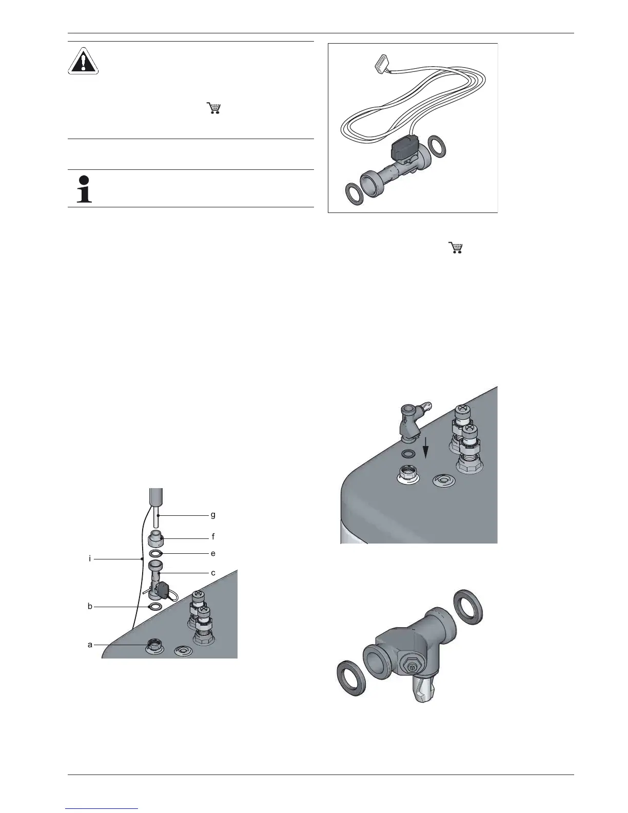
FlowGuard
The FlowGuard FLG (fig. 4-19, 16 41 02) is available as an
accessory. It is a regulating valve with integrated flow indicator
which can be used to set the flow rate through the solar panel
array. The display range is 2...16 l/min.
1. Insert the seal in the flow connection (see fig. 4-18).
2. Mount the FlowGuard, and screw it tight.
3. Insert the seal and install the plug fitting into the input to the
FlowGuard.
4. Insert a prepared flow pipe into the plug fitting of the
FlowGuard.
CAUTION!
In the case of longer pipe runs with only a minimum
gradient, it is possible for water pockets to develop
due to thermal expansion of the plastic pipes between
the mounting points with siphon action:
Ɣ Use support cups (TS 16 42 45).
Ɣ Always make sure that pipe runs have a
continuous gradient of at least 2 %.
Note the direction of flow when installing the FlowSen-
sor.
Fig. 4-16 Mounting FlowSensor FLS
Fig. 4-17 FlowSensor FLS supplied with 3 m cable
Fig. 4-18 Work step 1+2
Fig. 4-19 Accessory FlowGuard FLG