4 x Installation
FA ROTEX Solaris RPS4 - 06/2015
9
4 Installation
4.1 System concepts
ROTEX solar systems are usually built according to one of the
following system concepts. Information concerning hydraulic
system incorporation with example schematics can be seen in
chapter 8 "Hydraulic system connection".
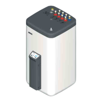
4.1.1 Parallel connection
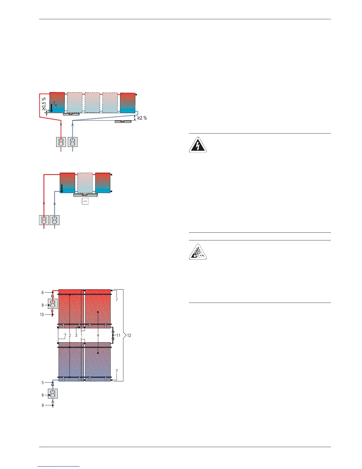
4.1.2 Serial connection
As an alternative to the parallel mode described in this manual,
and if necessary, a maximum of 3 solar panels can be mounted
one above the other. Solar panels or solar panel fields mounted
one above the other must be connected in series (fig. 4-3).
4.2 Installing the control and pump unit
Fig. 4-1 Solar panel field with a connection at each end
(recommended)
Fig. 4-2 Solar panel field with both connections at one end (max. 3 so-
lar panels)
Fig. 4-3 Alternative solar panel arrangement
T
K
1 Collector connector
2 Mounting rail
3 Solar panel securing hook
4 Solar panel
5 Return panel connection
6 Flow panel connection
7 Collector sealing cap
8 Roof penetration boxes for inflow/return flow
9 Solar return line
10 Solar flow line
11 Series panel connector
12 Solar panel array (2x 2 panels)
Tab. 4-1 Legend for fig. 4-3
WARNING!
Live parts can cause an electric shock on contact and
cause life-threatening burns and injuries.
Ɣ Before beginning work on the boiler switching
panel or the solar controller, disconnect the
devices from the power supply (switch off fuse,
main switch) and secure against unintentional
restart.
Ɣ Electrical installations must always be carried out
by qualified electrical technicians in conformity
with the relevant electrical guidelines and the
regulations of the electric utilities company to
prevent hazards from damaged electric wiring.
Ɣ Comply with the relevant safety at work regula-
tions.
DANGER!
Leaking gas in the immediate proximity of electrical
components can cause an explosion.
Ɣ The Control and pump unit RPS4 and electrical
components should not be installed in locations
where there is a danger of flammable gas
escaping.
Ɣ Pay attention to minimum distances from walls and
in shafts.