24
FA ROTEX Solaris RPS4 - 06/2015
6 x Control
6.2.9 Speed regulation of the solar operating
pump P
S
After reaching the switch-on conditions, the SOlaris R4 controller
leaves:
– the actuation of the solar operating pump P
S
at full output for
filling the solar system. This takes place dependent on the set
parameter value "Time P2" in [secs].
Î If the correctly adjusted FlowSensor detects a steady flow
before this time has expired, the solar system is com-
pletely filled with water.
– the actuation of the solar operating pump P
S
at full output up
to possible maximum flow rate of the system.
– the stepless output reduction of the solar operating pump P
S
,
until the calculated target spread "DT" maintains the set value
in accordance with fig. 6-2, or until the flow rate falls below the
minimum flow rate V2 (fig. 6-3 and tab. 6-1).
– the stepless increase in output of the solar operating pump P
S
after a safety period "t
2
" (fig. 6-3).
If the pump output is too low, the flow in the solar circuit can col-
lapse as a result of system and temperature influences. If the flow
rate falls below the value "V2" (fig. 6-3 and tab. 6-1), the con-
troller detects a flow rate breakaway, the last valid output stage
is saved as the minimum pump output value. Lower pump output
stages are automatically blocked.
The temperature-dependent output regulation of the solar oper-
ating pump P
S
then takes place between the determined
minimum and maximum outputs. The spread of "T
V
" and "T
R
"
(=T
V
– T
R
) is measured continuously and compared with the
target spread "DT". If the temperature spread between "T
V
" and
"T
R
" is too great, the pump output (max. 10 stages) and thus also
the flow rate through the solar panel is increased until the target
spread is achieved. If the spread is too small, the pump output is
reduced (fig. 6-2). The current pump output is displayed during its
active running time in the operating display "Throughput", next to
the throughput measured value in percent. A typical operating se-
quence of a modulating solar system is shown in fig. 6-3.
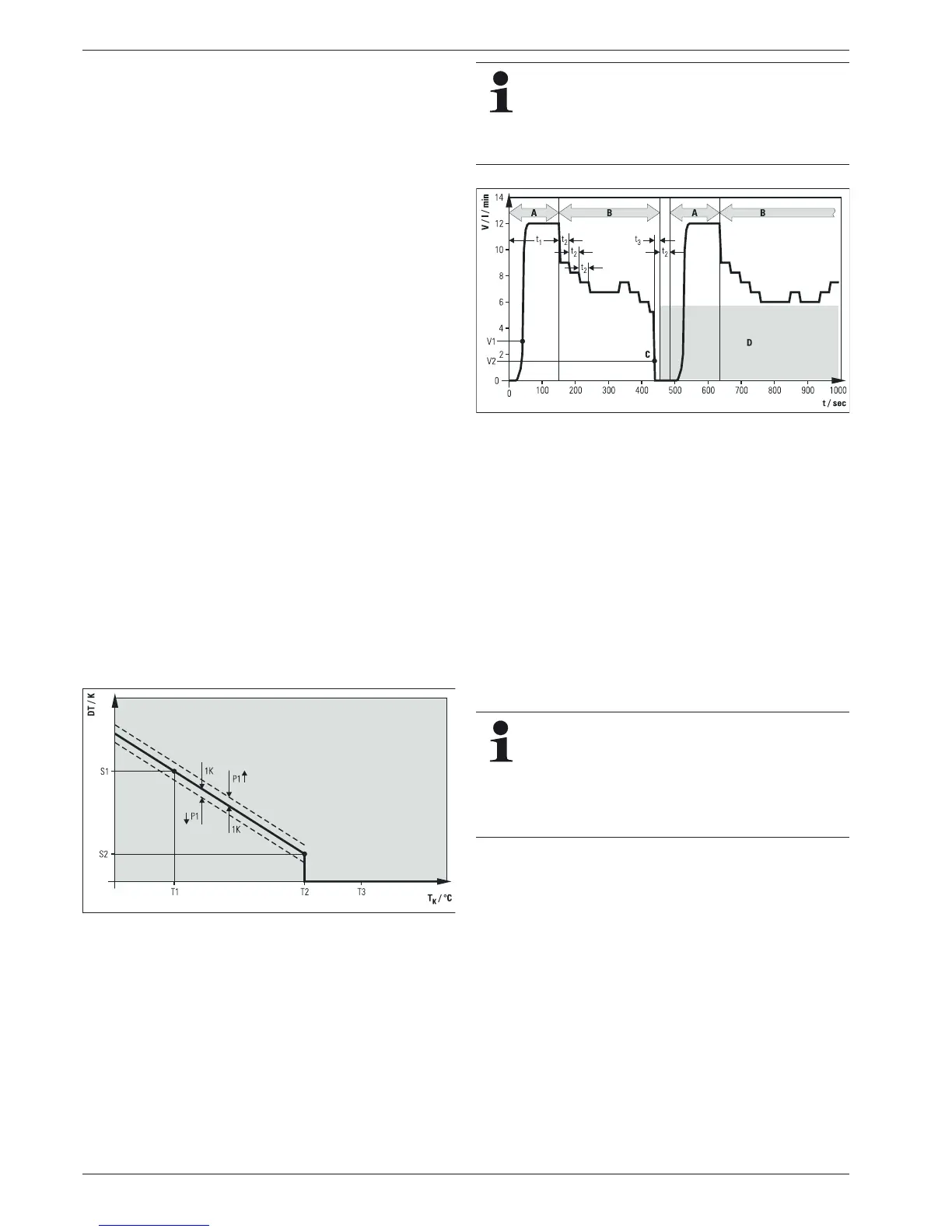
Fig. 6-2 Pump output control as a function of temperature difference
Fig. 6-3 Example for modulation operation with flow-caused block of
low pump stages on systems with FlowSensor
6.2.10 Total Reset Function
The device reacts to a total reset with a new start (self-test), all
parameters are reset to the factory settings and then all the
blocked pump output stages are released. The reset takes place:
Ɣ Via menu path: Activation by heating expert in the "System"
setting menu.
Ɣ By quick access: Simultaneous pushing of the OK and arrow
keys.
DT Target spread (calculated for the operating point)
P
S
Solar operating pump
S1 Top target spread ("Spread 1")
S2 Bottom target spread ("Spread 2")
T
K
Collector temperature
T1 Frost protection temperature ("T frost")
T2 Booster temperature ("T
K
max")
T3 Restart protection temperature ("T
K
perm")
— Target spread
- - Switching limits for pump modulation
n Pump output is increased
p Pump output is reduced
Controller is switched off and back on again:
– automatically blocked pump stages are released
again.
– the system is automatically regulated again.
– manually blocked pump stages (see chapter 6.3.8)
remain blocked.
A Start phase
B Operating phase (modulation)
C Interrupted flow
D Low pump output stages are automatically blocked after a flow
breakaway
P
S
Solar operating pump
t Time
t
1
Minimum running time of solar operating pump P
S
at maximum
output ("Time P2")
t
2
Stabilisation time
t
3
Interruption detection period (10 s)
V Solar circuit flow
V1 Minimal flow rate in the start phase
V2 Minimal flow rate in the operating phase
A total reset deletes all individual settings and the event
memory is deleted. All calculated values (info parame-
ters) are set to zero.
If this total reset function is triggered via the menu path,
the total thermal yield remains. This value is also
deleted using the quick access via the button combina-
tions.