5 x Start-up and decommissioning
FA ROTEX Solaris RPS4 - 06/2015
19
5.2 Decommissioning
5.2.1 Temporary shutdown
The ROTEX solar system can be shut down temporarily by
switching the main switch off on the Solaris R4 controller or by
separating the mains plug from the power supply.
If there is a danger of frost:
– the ROTEX solar system must be taken into operation
again
or
– suitable antifreeze measures must be applied to the con-
nected heating system and hot water storage tank
(e.g. draining).
Draining the storage tank
Ɣ Separate all power circuits of the solar and heating system
from the power supply and secure against inadvertent
switching on again.
Ɣ GCU compact only: Close gas stopcock.
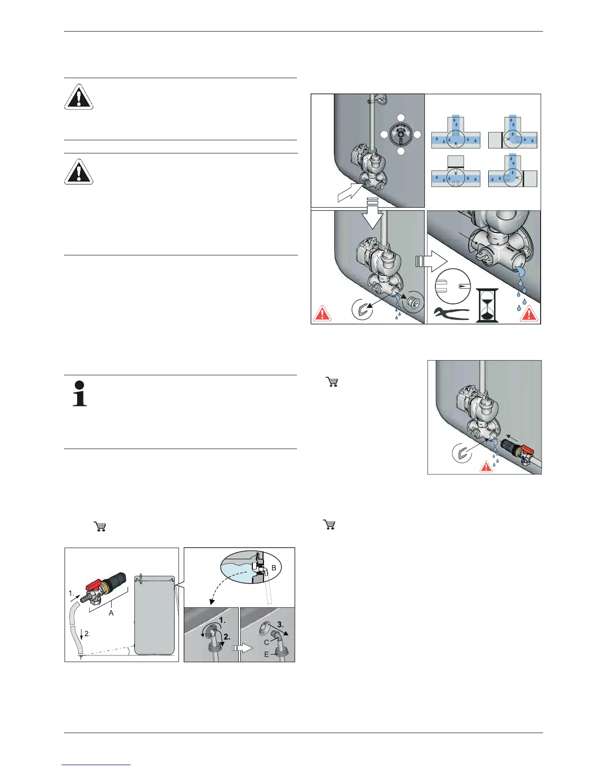
Ɣ Connect the drain hose to the filling and draining valve (KFE
BA, 16 52 15) (fig. 5-1, item A) and run to a drainage
point that is at least soil deep.
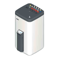
Ɣ Adjust the valve insert on the connecting angle so that the
path to the blind plug is blocked off (fig. 5-2).
Ɣ Remove the blanking plug from the connecting angle
(fig. 5-2) and place a suitable collection trough beneath the
unit.
Ɣ Open the KFE valve on the KFE filling connection (KFE BA,
16 52 15).
Ɣ Adjust the valve insert on the connecting angle so that the
flow to the drain hose is opened (also refer to fig. 5-2) and
drain the water content of the storage tank.
CAUTION!
A heating system which is shut down can freeze in the
event of frost and may suffer damage.
Ɣ Drain the heating system that is shut down if there
is danger of frost.
CAUTION!
Pumps that remain switched off for an extended period
can seize up.
With temporarily shut-down solar systems, the
protection function from seized pumps (pump kick
function) is also deactivated.
Ɣ Check for correct pump function when re-starting.
Seized pumps can normally be released again
manually.
If the danger of freezing will only last for a few days, the
very good heat insulation of the ROTEX means that it
need not be drained, as long as the storage tank tem-
perature is observed regularly and not permitted to fall
below +3 °C. This does not, however, provide any pro-
tection against frost for the connected heat distribution
system!
Fig. 5-1 Connecting the drainage hose
Fig. 5-2 Shutting off the valve insert and removing the blanking plug
from the connecting angle
Ɣ Insert the KFE filling
connection (KFE BA,
16 52 15) into the
connection elbow and
secure with the clamp
(fig. 5-3).
Fig. 5-3 Assembling the KFE fill-
ing connection in the
connecting elbow
1.
2.
X
4
3
2
1
G
X4
X1
X3
X2
X4
4.
3.