6 x Control
FA ROTEX Solaris RPS4 - 06/2015
25
6.2.11 Frost protection function
As soon as the solar panel temperature "T
K
" falls below "T frost"
(factory determined frost protection temperature), the frost pro-
tection function is activated. It remains activated for 24 h after the
limit temperature has been exceeded.
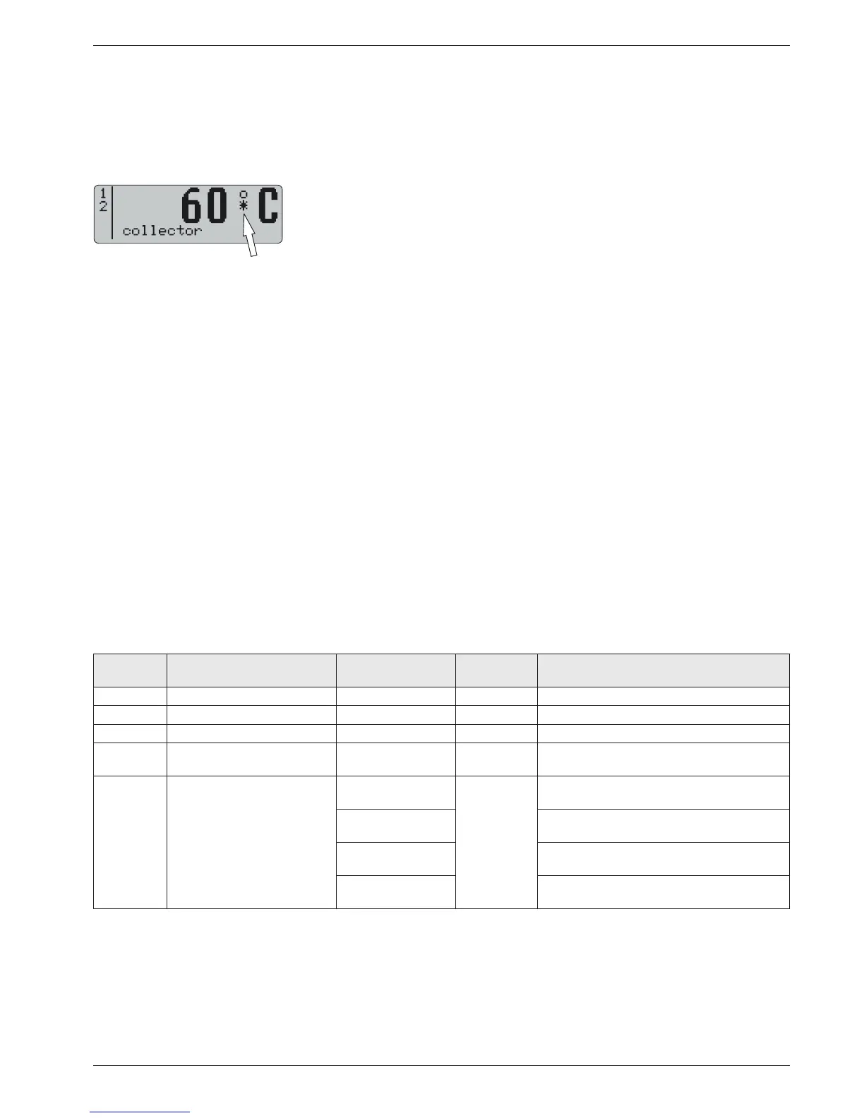
While frost protection is active a star icon is shown in the
standard temperature display.
The solar system only starts up with active frost protection if the
switch-on condition is fulfilled and the solar panel temperature
"T
K
" exceeds the value "T
K
save" (factory setting 70 °C). The
solar operating pump P
S,
after switching on, runs at least for the
time defined in the parameter "Time P2", even if the switch-off
temperature condition is reached before that.
If necessary, (e.g. for long connecting lines outdoors), this
minimum start run time can be extended by the heating expert by
an adjustable time ("Time frost"). This prevents the build-up of ice
in the connecting pipe.
The status of the frost protection function "FR active" shows
whether the function is activated or deactivated (fig. 6-7). The
heating expert can switch the function on and off manually.
The position of the solar panel temperature sensor can be
adjusted in the parameter "TK
pos
".
For optimising the frost protection, the solar panels must be in-
stalled with the sensor position "Bottom".
The parameter "TK
pos
" must be set to the actual mounting po-
sition of the solar panel temperature sensor (see section 6.3.7).
Enhanced frost protection function
As soon as the Solaris R4 controller detects a solar panel tem-
perature "T
K
" under -5 °C (non usable parameter "T frost off"), the
enhanced frost protection function becomes active. This com-
pletely blocks the pump operation - also in manual mode.
The function remains active for another 24 hours after exceeding
this threshold temperature.
The enhanced frost protection function is indicated by a flashing
star symbol on the display of the Solaris R4 controller. The
function cannot be switched off manually.
6.2.12 Leak protection function
If, after switching on the solar operating pump P
S
and expiry of
the filling time "Time P2", a minimum flow start phase "V1" in
accordance with tab. 6-1 is not detected at the FlowSensor, then
there may be:
– a defect of the FlowSensor, or
– a leak in the solar system.
In order to prevent the entire buffer water volume from being
pumped out of the system, the solar operating pump P
S
is
switched off for 2 hours, and the error message "W" flashes in the
left-hand column on the display.
If this fault occurs 3 times in a row, without reaching the minimum
flow rate start phase "V1" in the interim, the solar operating pump
P
S
switches off long-term and the error message "F" appears in
the left-hand column on the display.
Ɣ Replace the defective FlowSensor or repair the leak.
Ɣ Delete the error messages by "Switching OFF/ON" on the
main switch.
Î The system is then ready for operation again.
6.3 Adjustment and menu guide
Tab. 6-2 shows an overview of the available measuring points
and the associated display formats. Tab. 6-3 summarises the
views of the calculated parameters.
Tab. 6-2 Overview of measurement points
Fig. 6-4 Operating display with active frost
protection
Measuring
point
Designation
Display
Measuring range Resolution Sensor
T
K
Collector temperature -30 to 250 °C 1 K Pt 1000 temperature sensor
T
R
Return flow temperature 0 to 100 °C 1 K PTC temperature sensor
T
S
Storage cylinder temperature 0 to 100 °C 1 K PTC temperature sensor
T
V
Flow temperature 0 to 100 °C 1 K
FlowSensor (all types) with
voltage output 0.5 to 3.5 V
V Flow
0.0 to 12.0 l/min
0.1 l/min
FlowSensor FLS12 with
voltage output 0.36 to 3.5 V
0.0 to 20.0 l/min
FlowSensor FLS 20 with
voltage output 0.36 to 3.5 V
0.0 to 40.0 l/min
FlowSensor FLS 40 with
voltage output 0.36 to 3.5 V
0.0 to 100.0 l/min
FlowSensor FLS 100 with voltage output
0.36 to 3.5 V