12
FA ROTEX Solaris RPS4 - 06/2015
4 x Installation
4.2.3 Installing temperature sensor
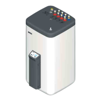
1. Bend over the contact springs on both sensors (return
temperature sensor, storage tank temperature sensor) and
insert into the sensor tube.
2. Position the return flow temperature sensor in the sensor tube
at approx. 130 cm insertion depth (cable tie).
3. Position the storage cylinder temperature sensor in the
sensor tube at approx. 70 cm insertion depth (cable tie).
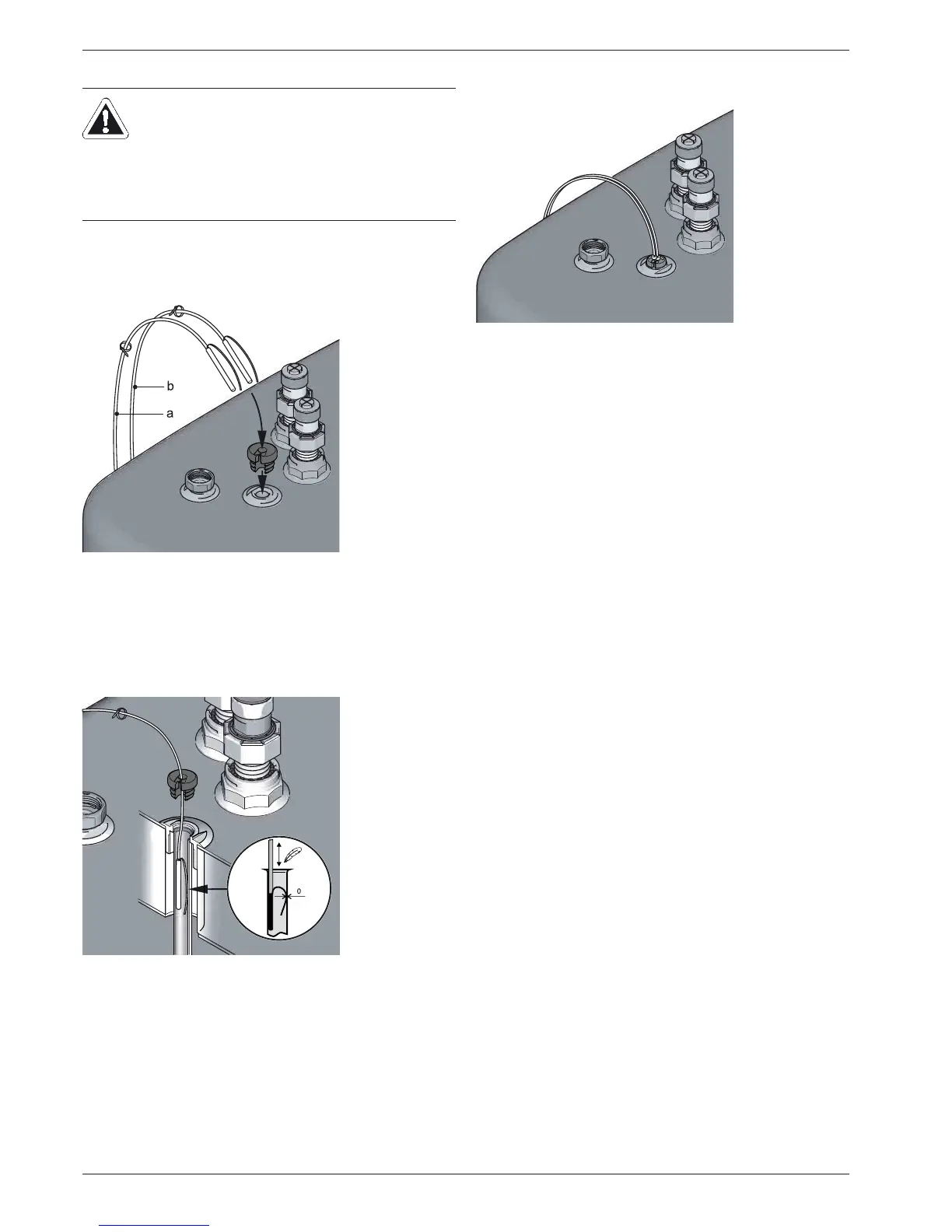
4. Push the sealing plug into the well, and run the cables.
4.2.4 Preparing and fitting the control system
Requirements
– For electrical connections and consumable electrical materi-
als (cable, insulation, etc.), follow all valid country-specific
guidelines.
– For every fixed mains connection, use a separate EN 60335-
1 disconnector for all-pole disconnection from the power
mains and a GFCI circuit breaker with a reaction time 0.2 s.
Permissible cable types at the terminal strip:
– Single core 2.5 mm
2
– Multi-core 2.5 mm
2
– Multi-core with wire end sleeves with insulating collar
1.5 mm
2
– Multi-core with wire end sleeves without insulating collar
2.5 mm
2
CAUTION!
On no account may the storage cylinder temperature
sensor of the boiler controller be inserted more than
75 cm into the sensor well. A sensor that is inserted
too deeply can lead to overheating of the consumption
water section, as well as a "hang-up" of the control unit
during the storage cylinder charging phase.
a Solaris return flow temperature sensor
b Solaris storage cylinder temperature sensor
Fig. 4-20 Work step 1
Fig. 4-21 Work step 2+3
Fig. 4-22 Work step 4