4 x Installation
FA ROTEX Solaris RPS4 - 06/2015
13
Electrical connection
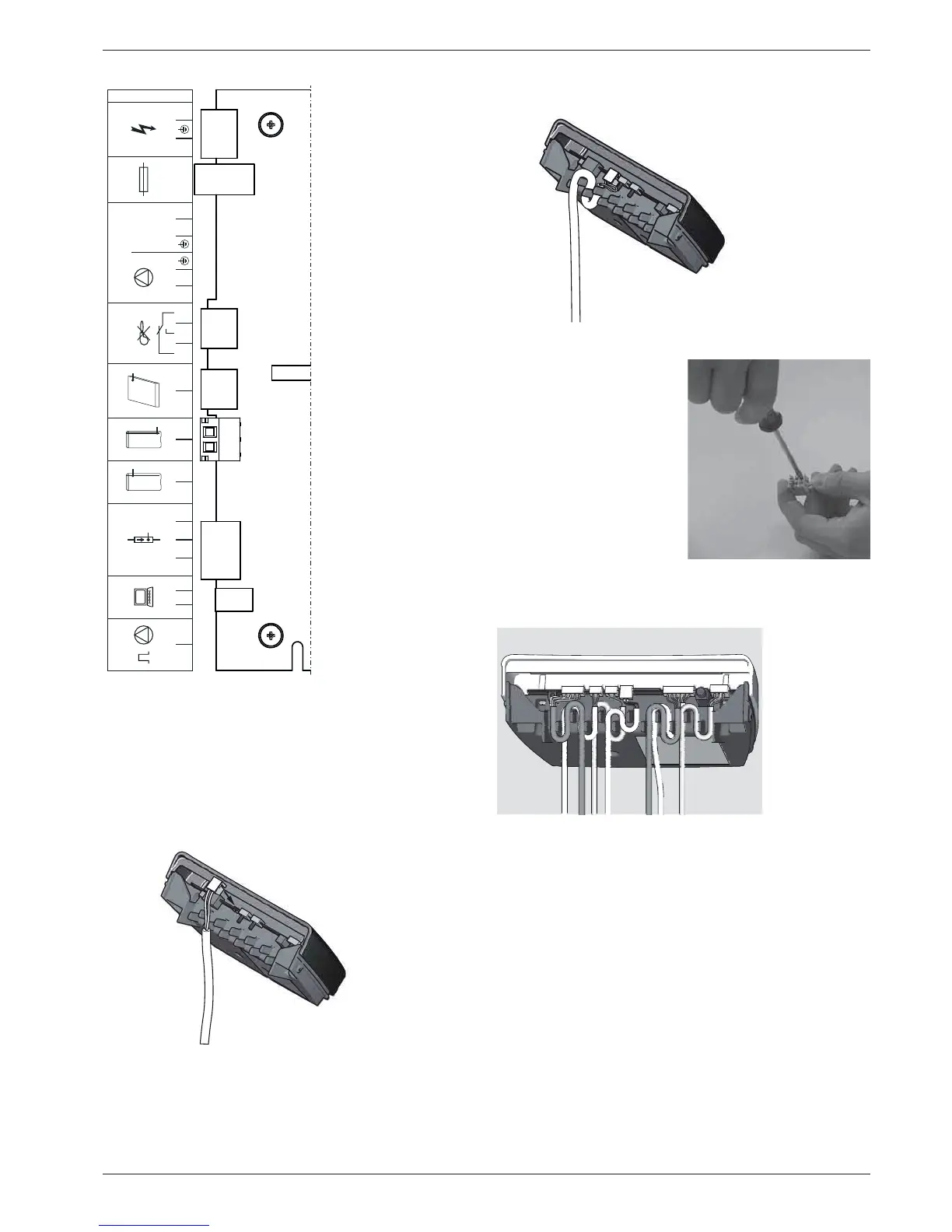
1. Fix the cable supplied to the back of the control system using
the edge connectors. The connectors are polarised to prevent
errors. A connecting diagram is provided in the control unit
cover.
2. To ensure reliable tension relief, all cables should be run
through the respective labyrinths.
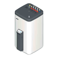
4. Insert the plug at the edge of the board on the controller, at
position TK (2-pin, see fig. 4-23).
BSK Burner inhibit contact
CONF
Programming socket for
Software update
FLS FlowSensor
TS Storage cylinder temper-
ature sensor
TR Return flow temperature
sensor
TK Collector temperature
sensor
P
S
Solar operating pump
F1 Fuse
Power
Mains supply
Fig. 4-23 Connection assignment
Fig. 4-24 Work step 1
FLS TRTS TK
BSK
P1 F1
250V
T2A
POWERCONFPWM
007.16 108 99_00
n.b.
NN LL11111113
3
22222224
3
Fig. 4-25 Work step 2
3. Connect the solar panel
temperature sensor line
(integrated in the
connection line) to the plug
terminals.
Fig. 4-26 Work step 3
Fig. 4-27 Basic wiring: FlowSensor, storage tank, return, solar panel
sensor, pumps and mains wiring