Hardware Installation and Reference Guide Product Overview
14
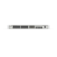
2. Power status LED (PWR1)
3. Power status LED (PWR2)
4. MGMT port status LED
5. Console port
6. 10/100/1000Base-T Ethernet port
8. Switch port status LED
9. USB port
10.Mini USB port
11. MGMT port
12.10GE SFP+ port
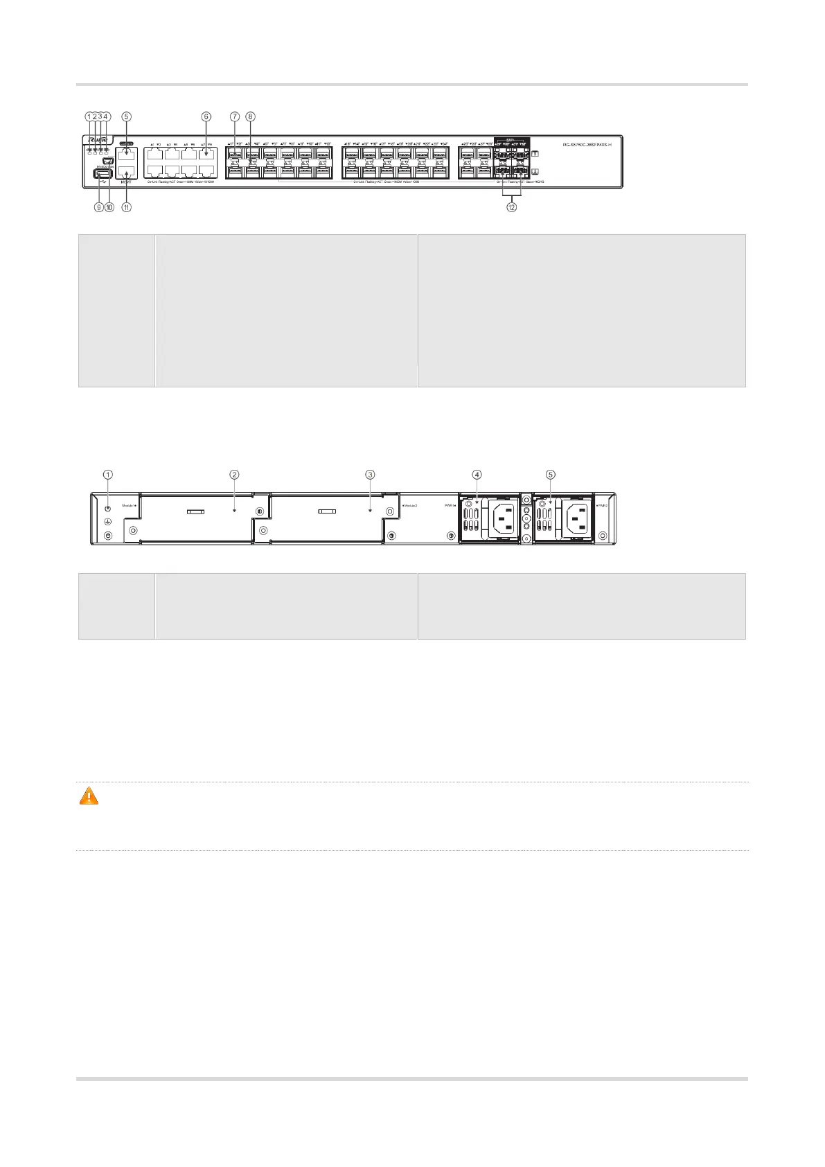
Back Panel
Figure 1-11 Back Panel of RG-S5750C-28SFP4XS-H
2. Expansion module slot 1
3. Expansion module slot 2
Power Supply
The RG-S5750C-28SFP4XS-H supports two power modules. For details, see the section “Power
Modules”.
Dual-power input: The switch can be powered by one power module, or two power modules. When both
two modules are available, the switch is powered in current sharing mode.
When the switch is powered by the dual-power modules, if the system working power is greater
than the capacity of single power module, power redundancy cannot work; if one power module
fails, the switch system will be affected.
Heat Dissipation
The RG-S5750C-28SFP4XS-H is designed with left and right fans for heat dissipation, thereby ensuring
the normal function of the device in the specified environment. Maintain a minimum clearance of 10 cm
around the device for proper air circulation.
Figure 1-12 Flow Scheme of Heat Dissipation
 Loading...