Hardware Installation and Reference Guide Appendix C Lightning Protection
71
Appendix C Lightning Protection
Installing AC Power Arrester (lightning protection cable row)
The external lightning protection cable row shall be used on the AC power port to prevent the switch
from being struck by lightning when the AC power cable is introduced from the outdoor and directly
connected to the power port of the switch. The lightning protection cable row is fixed on the cabinet,
operating table or the wall in the machine room using the line buttons and screws.
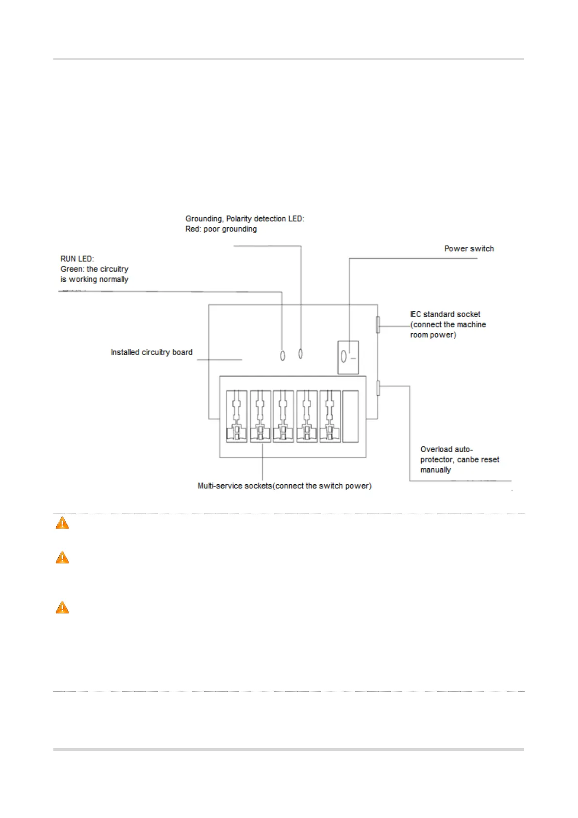
Figure C-1 Schematic Diagram for the Power Arrester
The power arrester is not provided and the user shall purchase it to address the practical
requirement. Make sure that the PE terminal of the power arrester has been well-grounded;
After connecting the switch AC power plug to the socket of the power arrester (lightning protection
socket), lightning protection function implements if the RUN LED is Green and the ALARM LED is
OFF.
If the ALARM LED on the power arrester is Red, you shall check what the reason is, poor
grounding connection or the reversed connection of the Null and Live lines: Use the multimeter to
check the polarity of the power socket for the arrester when the LED is Red, if the N line is on the
left and the L line is on the right, the arrester PE terminal is not grounded; if the L line is on the left
and the N line is on the right, the polarity of the arrester power cable shall be reversed; if the LED
is still Red, it is confirmed that the arrester PE terminal has not been grounded.
Installing the Ethernet Port Arrester
 Loading...