Hardware Installation and Reference Guide Product Installation
52
If you want to use RG-M5000E-DC500P to provide power for RG-S5750-24GT/8SFP-P or RG-
S5750-48GT/4SFP-P, please refer to the following figure and installation steps.
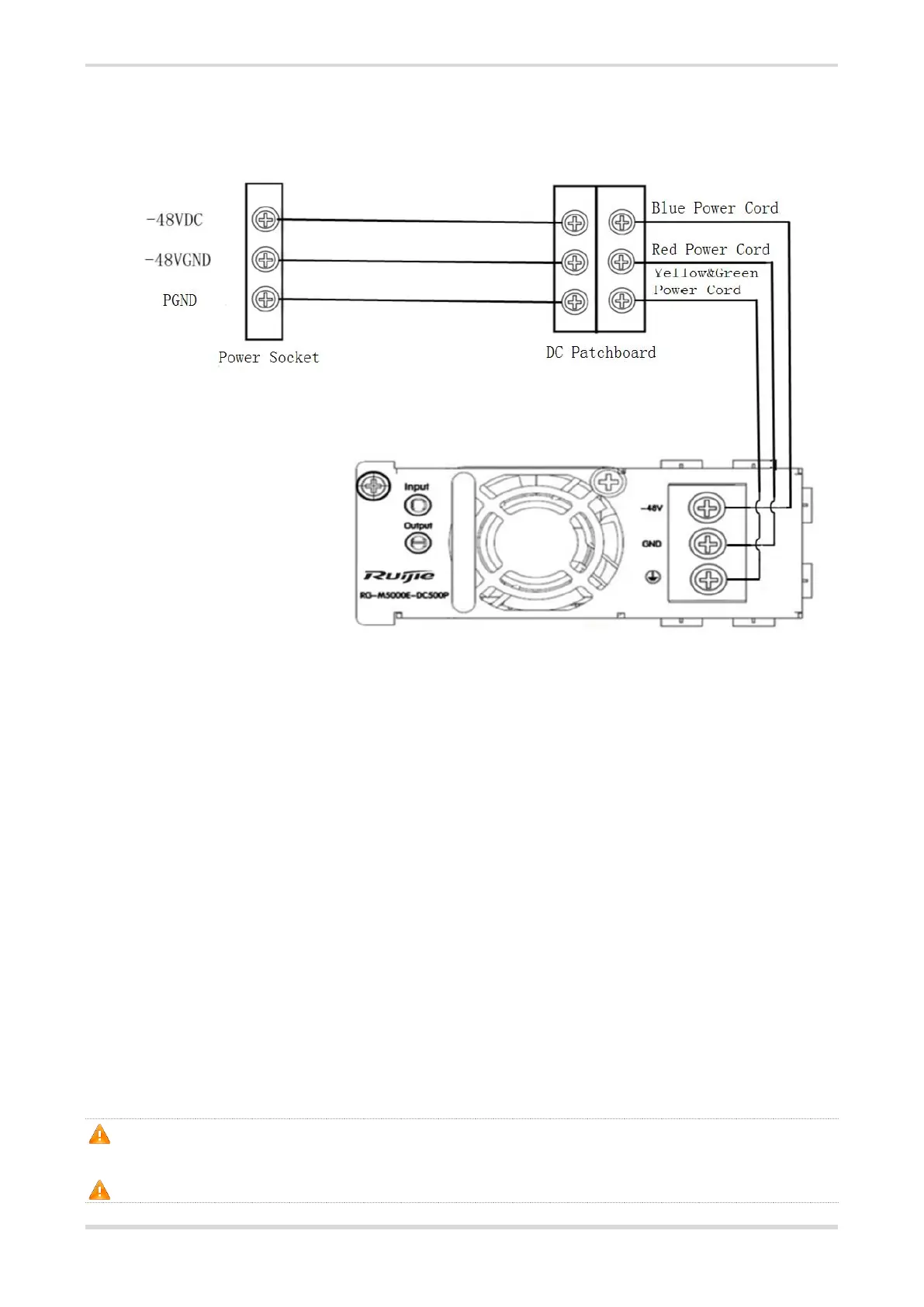
Figure 3-10 Power Supply Connection
Installation Steps
Take out power supply RG-M5000E-DC500P and DC power cord, and insert the power supply
into the power slot.
Take out the insulating cover for power input and loosen the screw.
Plug the power cord into the DC socket.
RG-M5000E-DC500P is supplied with connection cables. The -48V power cable should be blue.
The grounding cable should be black. The PGND is yellow and green.
3.6 Grounding the Switch
RG-S5750H has a PGND on the back panel. First connect the PGND to the grounding lug of the rack
and then connect the grounding lug to the grounding bar of the equipment room.
Precautions
The sectional area of the grounding wire should be determined according to the possible maximum
current. Cables of good conductor should be used.
Do not use bare wire.
The grounding electric resistance should be less than 1Ω.
To guarantee the security of the body and the device, the switch must be well-grounded. The
grounding resistance for combined grounding should be less than 1Ω.
The AC power cable should be connected to the output socket with grounding connector.
 Loading...