7 SERVICE
18
3792
1
2
3
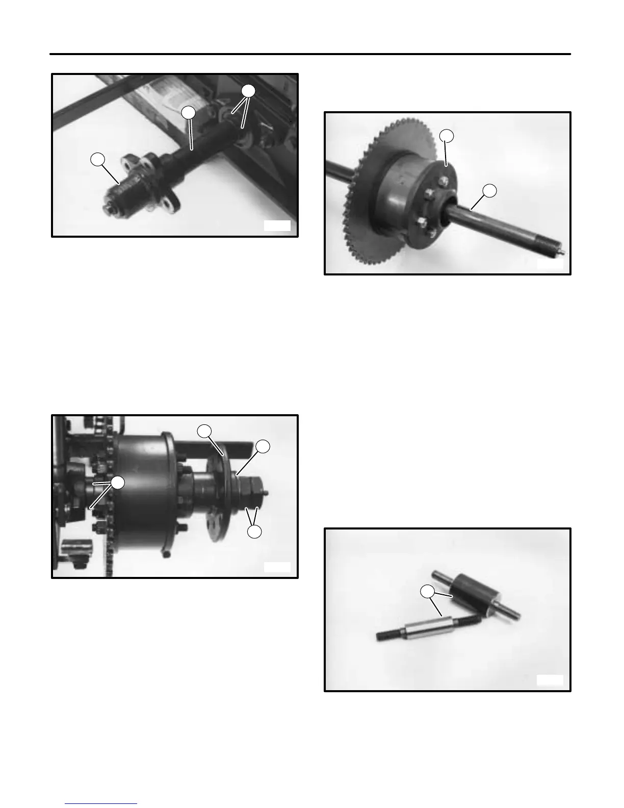
FIGURE 22
1. Hub
2. Spacer
3. Locking Collar Set Screws
4. On right side of unit, remove drive chain.
5. Loosen set screws in locking collar on pillow block
and pull differential and axle out right side. (See
FIGURE 23.)
3793
2
1
4
3
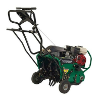
FIGURE 23
1. Locking Collar Set Screws
2. Hub
3. Washer
4. Axle Nuts
6. Remove axle nuts, washer and hub from axle.
7. Slide differential in toward center of axle and remove
key. Then slide differential off end of axle. (See
FIGURE 24.)
NOTE: If axle is secured in vise to remove differential,
use shop towel or other protection to prevent dam-
age to axle.
3794
1
2
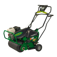
FIGURE 24
1. Differential
2. Key
8. Remove six nuts and separate parts of the differen-
tial. Remove and clean all internal parts. Inspect for
damage and wear.
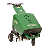
NOTE: Some differentials will have spacers with
threaded studs at both ends(as shown in
FIGURE 25). Some will have screws that are
inserted from the sprocket end and spacers that
slide onto them.
When ordering parts, spacers with threaded studs
will be supplied and can be used interchangeably
with the other style.
Be sure to order nuts for both ends of spacer.
3795
1
FIGURE 25
1. Spacers With Threaded Studs
NOTE: Many times, when removing spacers with nuts
on both ends, only one nut will loosen. The remain-