7 SERVICE
20
3800
1
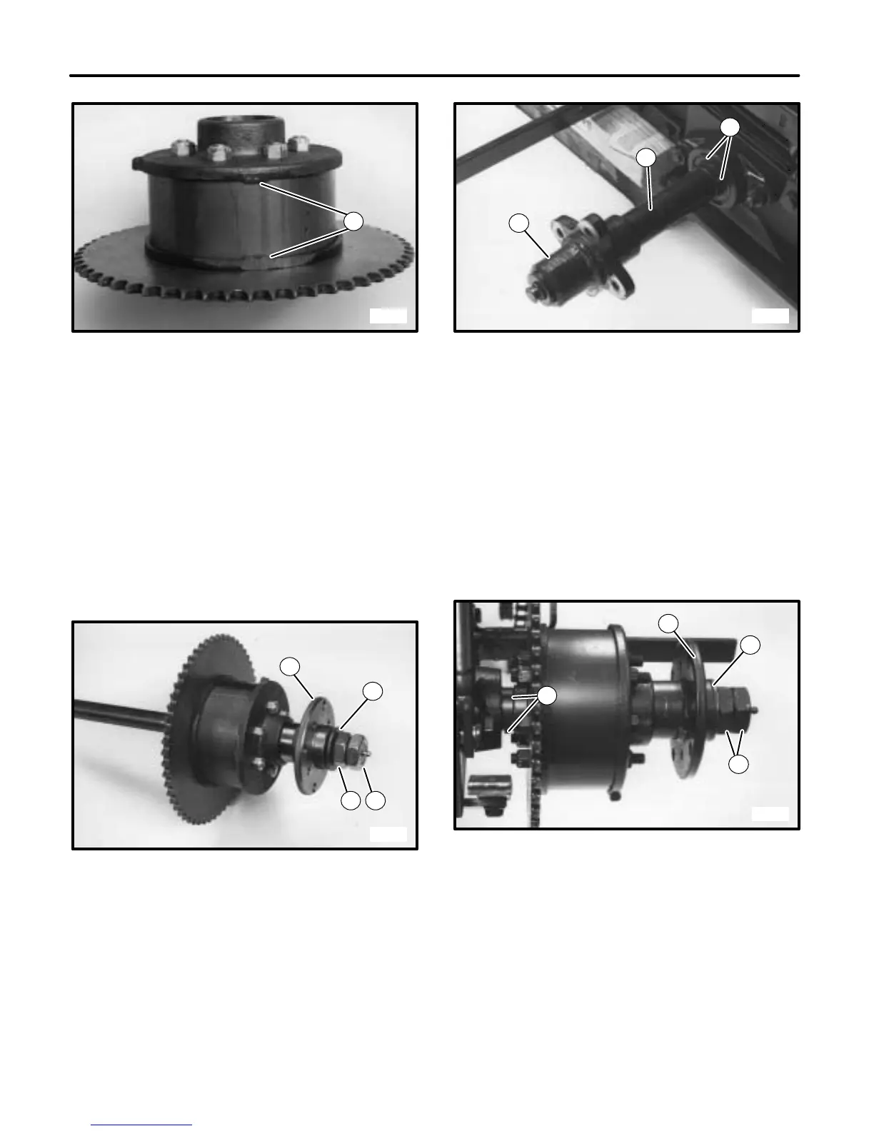
FIGURE 30
1. Alignment Marks
14. Turn assembly over so nuts are on the bottom and
install sprocket. Loctite remaining nuts and start onto
studs. Torque all nuts to 25–30 lbs. ft. (34–41N·m).
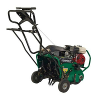
15. Slide differential onto axle, past the keyway. Install
key and slide differential back over key engaging key
in keyway of axle shaft gear.
16. Install hub, washer and axle nut and jam nut. Leave
nuts loose. (See FIGURE 31.)
3801
1
43
2
FIGURE 31
1. Hub
2. Washer
3. Axle Nut
4. Jam Nut
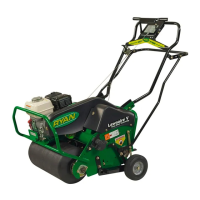
17. Slide axle back into unit from right side. Install
spacer, hub, lockwasher and axle screw onto the
axle from left side of unit. Tighten the axle screw.
(See FIGURE 32.)
3792
1
2
3
FIGURE 32
1. Axle Screw And Lockwasher
2. Hub
3. Spacer
4. Set Screws
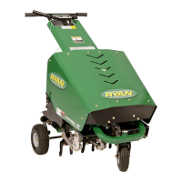
18. Snug the axle nut (refer to FIGURE 31) against the
hub to set the position of differential and axle. Tighten
the set screws in pillow block collars on both sides of
unit (item 4 in FIGURE 32 and item 1 in FIGURE 33).
Torque the axle nut to 50 in. lbs. (5.5 N·m) then back it
off 3/4 of a turn and secure it in place with the jam nut.
(See FIGURE 33.)
3793
2
1
4
3
FIGURE 33
1. Set Screws
2. Axle Nut
3. Locking Nut
19. Lubricate fitting on end of shaft until lubricant comes
out between washer and hub.
20. Install chain and wheels (see Chain Adjustment.)
21. Lower unit and replace all shields before operating
unit.