NMEA PCB in SAILOR 6390 Navtex Receiver
A-2 Appendix A: Technical specifications 98-139768-A
A.2 NMEA PCB in SAILOR 6390 Navtex Receiver
(Extract from IEC 61162-1)
• NMEA + (A) and - (B) are indicated at the terminals on the PCB
• Max output drive is 40 mA
• A list of supported sentences and data fields are given in
• Load of the input circuit is 1.8 mA @ 1.85 V
• Compliance with IEC61162-1 (4
th
edn.)
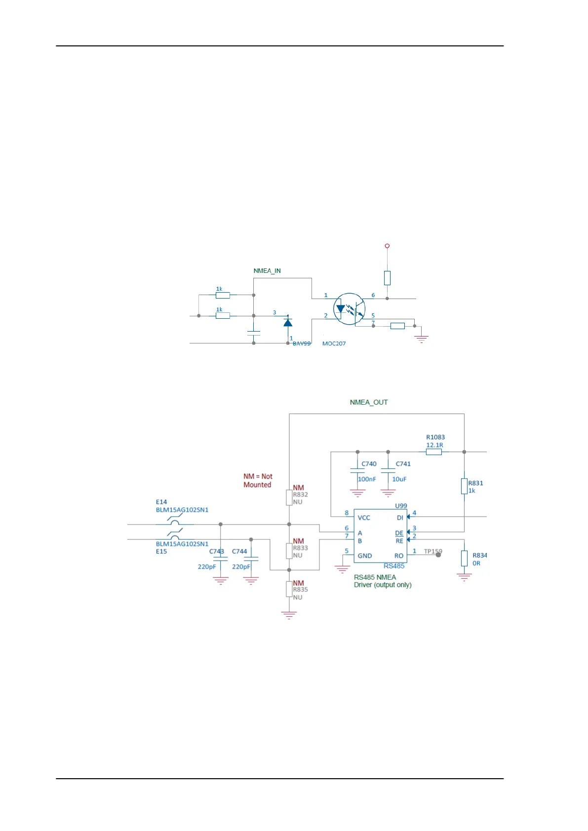
U99 is a MAX3483 which is an RS-485/RS-422 transceiver. In this circuit it is only used as a
transmitter. E14, E15, C743 and C744 is for EMC immunity filtering. R834 is to disable the
receiver in U99. R831 is to enable the transmitter in U99. C740,C741 and R1083 are for de-
coupling and to filter the supply voltage to U99.
Figure A-1: NMEA_IN diagram
Figure A-2: NMEA_OUT diagram