EB 8389 EN 95
Leakage sensor
Phase 2: A 0.30% band is placed around
the last point that the valve moved to. One
third of this band lies in front of the point
that the valve moved to and two thirds of the
band lies behind it. The band itself is subdi-
vided into eleven new measured points. Each
measured point is located at a distance of
0.03% to the next point. The valve moves to
the new points one after the other. After
reaching a point and after the 'Settling time
before level measuring' has elapsed, the
leakage sensor measures the sound pressure
level.
The reference test is successful when the dif-
ference between the rst and last newly de-
ned points is larger or equal to the adjusted
'Activation level'.
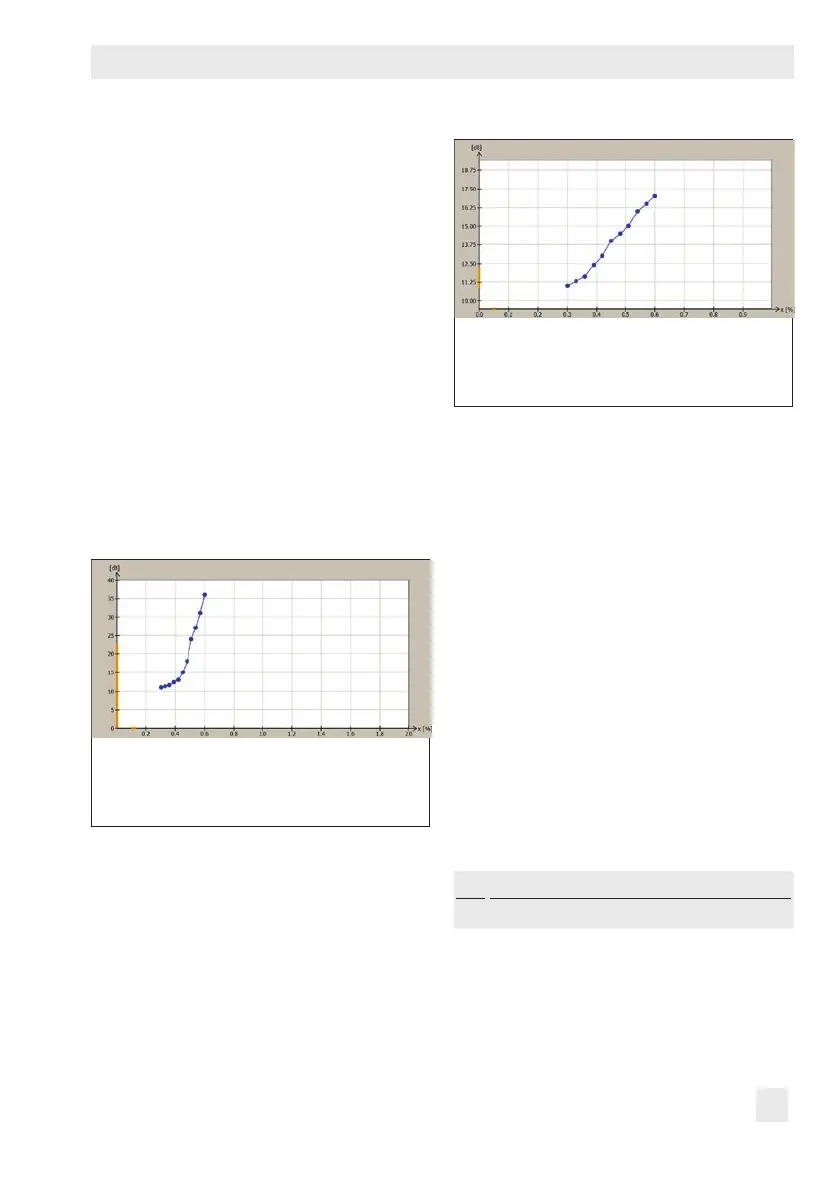
Phase 2 successful: The 'Activation level' (10 dB)
is reached between the rst and last newly de-
ned points. The reference test is successfully
completed.
If the 'Activation level' is not reached after
the valve has moved to all eleven newly de-
ned points, then the change in sound pres-
sure level is too low. In this case, phase 3
starts.
Phase 2 not successful: The difference in sound
pressure level between the rst and last newly
dened points is lower than 'Activation level' (10
dB). Phase 3 starts.
Phase 3: The valve moves to the user-dened
points valid for phase 1 one after the other.
This is plotted in a sound level vs. travel
graph. The graph shows where the point of
activation is and to which value the 'Activa-
tion level' must be reduced to allow the test
to be completed successfully.
Dening parameters
1. Switch to manual mode.
2. Dene parameters for reference test. See
Note concerning changing measured
points.
3. Start reference test.
The start of the reference test is docu-
mented in the Time stamp.
'd8' and 'tEST' are indicated in alternat-
ing sequence on the positioner display.
1.
Operation > Operating mode
1)
− Target mode (Code 0): Manual
 Loading...


