EB 5824-2 EN 13
Design and principle of operation
3.1 Fail-safe action
The actuator moves to the fail-safe position
whentheelectromagnetisde-energized.This
causes the actuator stem to be completely re-
tractedorextendedbythespringmecha-
nism.
TheType5825Actuatorisavailablewiththe
fail-safeaction:
Actuatorstemextends: upon supply voltage
failure,theactuatorstemextends.
Actuatorstemretracts: upon supply voltage
failure, the actuator stem retracts.
Î The fail-safe action must not be used to
control the valve position.
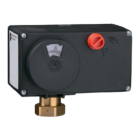
TheType5825Actuatordoesnothavea
handwheel (2) on the housing cover. Manual
override is possible, after removing the front
cover,usinga4mmAllenkey.Theactuator
returns to its original position as soon as the
Allen key is released.
TestingaccordingtoDINEN14597
TheTypes5825ElectricActuatorwithfail-
safeaction"actuatorstemextends"istested
bytheGermantechnicalsurveillanceassoci-
ation(TÜV)accordingtoDINEN14597in
combination with various SAMSON valves.
Tested versions are indicated on the name-
plate. They are listed in the Technical data
table.
The registration number is available on re-
quest.
3.2 Cover screws
The actuator housing cover is fastened using
TORX PLUS
®
screws,size10IP.
Î To loosen and tighten the screws, the fol-
lowingscrewdriverscanbeused:
− TORX
®
T10
− TORX PLUS
®
10IP
− Flat-bladescrewdriverwith0.8mm
bladethicknessand4.0mmbladewidth
3.3 Additional functions
Devicesin24Vversioncanbettedwith
limit contactsasadditionalfunction:
− Optionally, the actuators can be
equipped with two limit contacts, which
are actuated by continuously adjustable
cam disks.
− The supply voltage as well as the inputs
and outputs are not galvanically isolated.
− The two additional limit contacts are not
suitableforretrotting.

 Loading...