System Overview System Overview
SYSTEM CONTROLLER User’s Manual
9
ENGLISH
SYSTEM CONTROLLER User’s Manual
8
• All supported SPEED DOME functions can be controlled when the PTZ camera is
connected through the SVR-1650/1640/950.
• When connecting with an SVR-1630, only SPD series PTZ cameras can be employed.
•
When controlling a PTZ camera via an SVR-1630 there is a delay, and the response may be slow.
•
When controlling a PTZ camera with a sub-controller there is a delay, and the response may be slow.
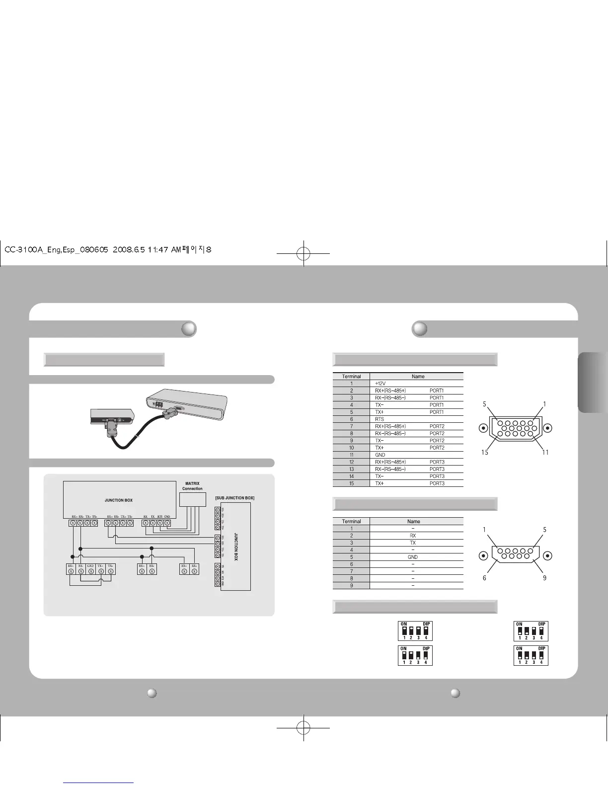
2. RS-485/422 Pin Layout (D_SUB_FEMALE)
3.RS-232C Pin Layout (D_SUB_MALE)
• RS-485 Termination ON • RS-422 Termination ON
• RS-485 Termination OFF • RS-422 Termination OFF
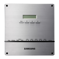
4. Junction Box DIP Switch
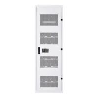
1-2 Connecting Junction Box and External Devices
1-1 Connecting Controller and Junction Box
[SVR-1650/1640/950/1630/430/440 connection]
* RX+ and TX+ / RX- and TX- must be short-
circuited.
[SVR-1630 connection] [PTZ connection]
(SPD-3300/3000/2300,
SPD-2500/2200/1600)
* RX+=DATA+
RX- =DATA
1. System Connections