Do you have a question about the Samwha DSP DSP-VIP-PL and is the answer not in the manual?
Details the panel mounting configuration for the DSP-VIP-PL.
Details the flush mounting configuration for the DSP-VIP-PM.
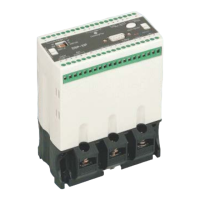
Details the physical components and layout of the converter unit.
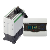
Details the physical components and layout of the loader unit.
Details the physical components and layout of the display meter.
Details the physical components and layout of the communication module.
Highlights user-friendly aspects and operational convenience of the relay.
Describes the advanced and integrated functions offered by the relay.
Illustrates the relationship between incoming voltage and load current.
Discusses compatibility with different ZCT ratings for protection.
Details the advanced protection classes offered by the device.
Explains the functionalities of communication modules like DSP-CM-44.
Describes the diverse indication methods and displays available.
Specifies line voltage ranges and adjustable settings.
Details current setting ranges and ground fault protection specifications.
Covers time setting parameters and operational tolerances.
Outlines control power requirements and trip relay specifications.
Specifies operating environment and logic input details.
Lists electrical withstand tests and digital communication standards.
Details protection against over and under voltage conditions.
Covers protection mechanisms for overload and overcurrent faults.
Explains protection for underload and undercurrent faults.
Describes protection against current and voltage unbalance.
Details protection for locked rotor and shock/stall conditions.
Covers protection against short circuits and ground faults.
Details over-temperature and phase loss protection features.
Explains protection against reverse phase sequences.
Shows how line voltage and load current are indicated.
Details indication for temperature and power factor.
Describes transfer timer and DC 4-20mA auxiliary functions.
Explains the password protection for operation.
Outlines terminal connections for external CT.
Outlines terminal connections for embedded ZCT.
Details the output signals for the main trip relay.
Details the output signals for auxiliary trip relays.
Details the output signals for Over/Under Voltage trip relays.
Describes accessing and setting parameters in Main Mode.
Describes accessing and setting parameters in Sub Mode.
Describes calibration procedures in Cab Mode.
Illustrates the navigation structure between different modes.
Explains operation of mode selection and set keys.
Details adjusting values and storing settings.
Explains how to start and stop the motor using keys.
Describes how to check preset values during operation.
Shows time-based trip characteristics for overload/overcurrent.
Illustrates protection curves for over/under voltage.
Details trip characteristics for shock/stall and ground fault.
Shows level alarms for overcurrent and transit time.
Displays indications for current-related trip events.
Displays indications for voltage-related trip events.
Provides inverse time-current curves for overcurrent.
Provides inverse time-current curves for ground fault.
Details logic input operations for LOP duty.
Details logic input operations for remote sensor duty.
Details logic input operations for PC and meter duties.
Details logic input operations for FWD/REV and EFI.
Shows display of basic factors like voltage, current, power.
Shows display of advanced factors like PF, temperature, time.
Illustrates direct communication between PC and DSP via RS-232.
Illustrates communication via RS-485/422 for center/PLC.
Provides guidance on handling communication modules.
Explains communication setup using a gateway.
Provides an overview of the PC operation program features.
Guides the installation process for the "Samdsp" program.
Explains how to monitor data using the PC software.
Shows physical dimensions of the converter/communication module.
Shows physical dimensions of the converter/loader unit.
Shows physical dimensions of the display meter.
Shows physical dimensions of the loader unit.
Lists available accessories for the product.
| Product Category | Relays |
|---|---|
| Manufacturer | Samwha |
| Model | DSP-VIP-PL |
| Contact Form | 1 Form A |
| Contact Rating | 10A 250VAC |
| Coil Voltage | 24VDC |
| Operate Time | 10ms |
| Release Time | 5ms |
| Insulation Resistance | 1000 MΩ min |
| Dielectric Strength | 1500VAC for 1 min |
| Ambient Temperature | -40°C to +85°C |