13
3. LED indicators
4 Operation
The LEDs contains Fault indicator, Load/battery capacity indicator, Bypass indicator,
utility power indicator, Inverter indicator, Battery indicator.
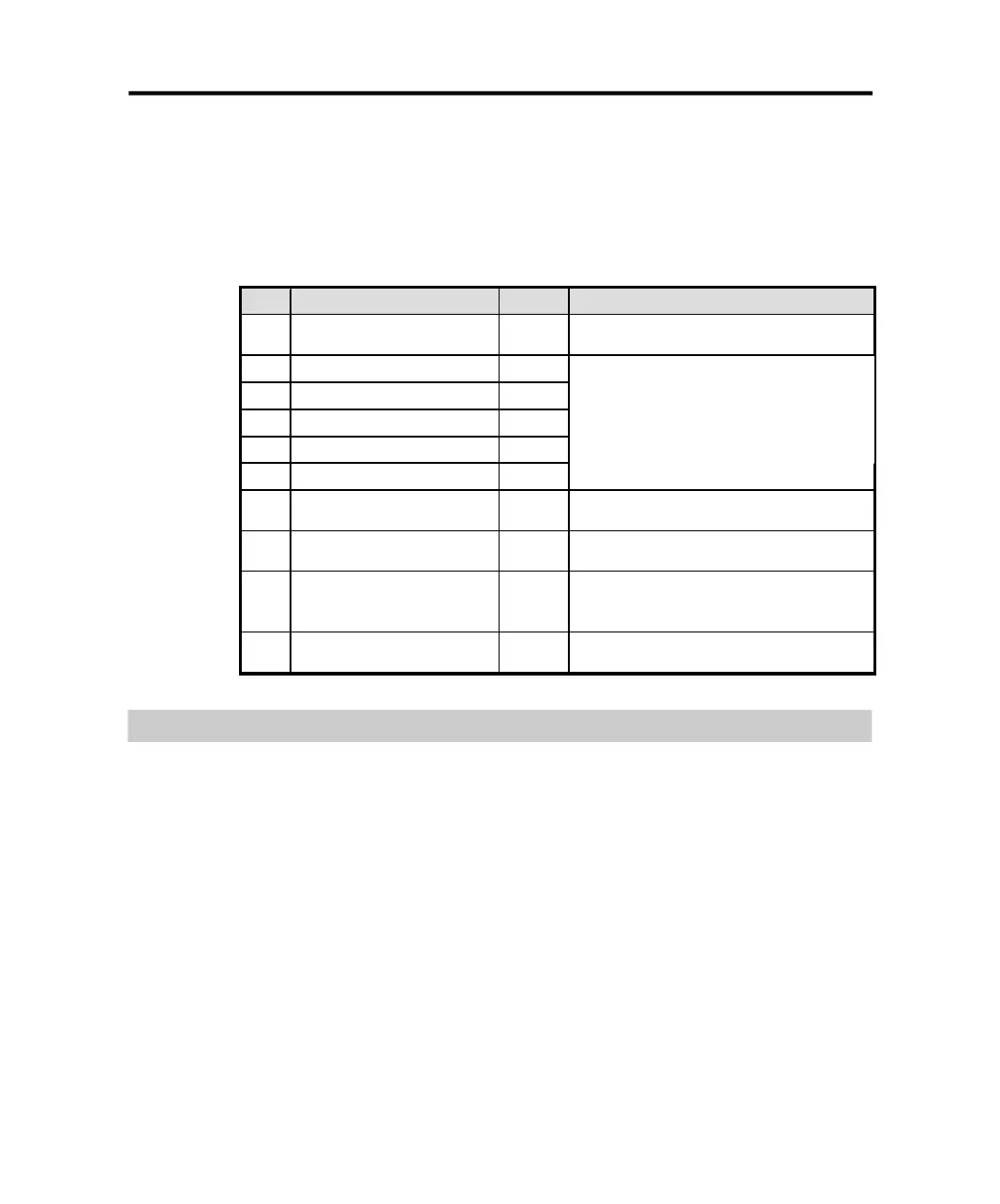
Table 4-1 Description of indicators
No. Indicator Color
Description
1#
Fault indicator
Red
When the indicator on, it shows that the UPS in
abnormal condition.
2#
Load/battery capacity
indicator
Orange
3#
Load/battery capacity
indicator
Green
4#
Load/battery capacity
indicator
Green
5#
Load/battery capacity
indicator
Green
6#
Load/battery capacity
indicator
Green
Show the capacity of load/battery:
1.Indicate the percentage of the load capacity in
normal mode and bypass mode
2. Indicate the battery capacity level in battery
mode.
7#
Bypass indicator
Orange
When the indicator on, it shows that the loading
current is supplied from the utility power directly.
8#
Utility power indicator
Green
When the indicator on, it shows that the utility
power is normal.
9#
Inverter indicator
Green
When the indicator on, it shows that the load
current is supplied from utility power or battery via
the inverter.
10#
Battery indicator
Orange
When the indicator on, it shows that the load
current is supplied from battery via the inverter.
Operation Mode
24.
4.2.1 Normal mode
In the normal mode, the display on the front panel is shown in the following
diagram. The utility power indicator and the inverter indicator are turn on. The
load/battery capacity indicator will be turned on in accordance with the load
capacity connected.
PDF created with pdfFactory Pro trial version www.pdffactory.com