SINUS MINI High performance Vector Control Inverter User Manual
16
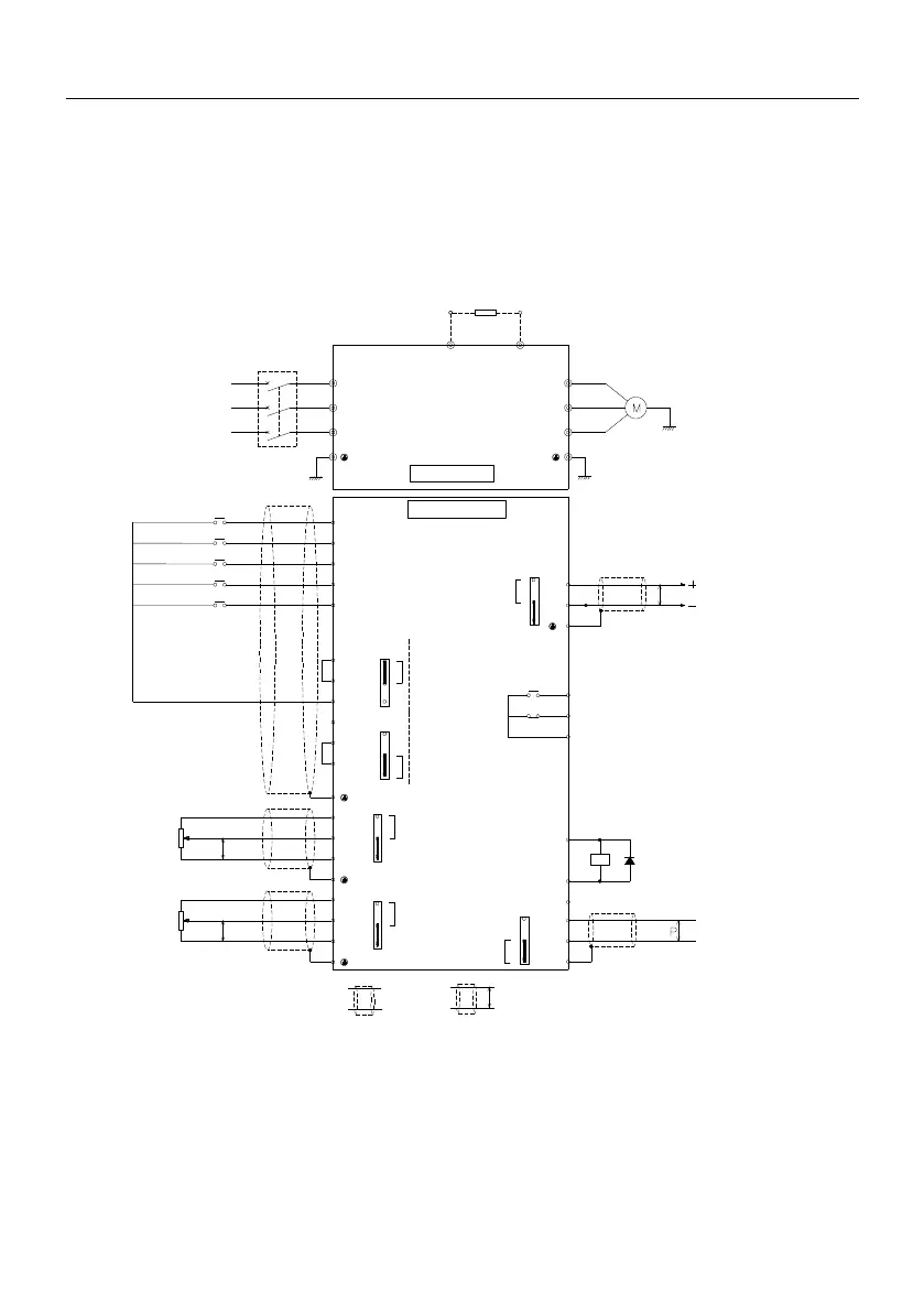
2.6 Terminal wiring
This section describes all the precautions and requirements that ensure the user's safe use of the
product, maximize the performance of the inverter, and ensure the reliable operation of the inverter.The
standard wiring diagram is as follows:
B
R
S
T
U
V
W
DI1
DI2
DI3
DI4
DI5/HD1
+10V
AI1
GND
10kΩ
P
AO1
GND
RC1
+24V
Y1
P
RA1
RB1
250V AC/1A
30V DC/1A
CM
P
R
S
T
+10V
AI2
GND
10kΩ
P
+24V
OP
CM
+24V
485+
485-
GND
OP
CM
3
2
1
J7
3
2
1
J7
Drain
drive(default)
source drive
3
2
1
J4
2-3short-circuit
AI1C 0-20mA DC
1-2 short-circuit(default)
AI1V 0-10V DC
3
2
1
J5
2-3short-circuit
AI1C 0-20mA DC
1-2
short-circuit(default)
AI1C 0-20mA DC
3
2
1
2-3short-circuit
AO1C 0-2mA DC
1-2 short-circuit(default)
AO1V 0-10V DC
3
2
1
J6
485
terminal
resistor
selecting
switch
Circuit breaker
Three phase AC
power supply
Power grounding
Motor
motor grounding
Multi function input 1
Multi function input 2
Multi function input 3
Multi function input 4
Multi function input 5
Braking Resistor
Main circult
Control circult
Analog output 1
Relay output1
Relay
Modbus
communication
RS485
Shielding
cable
Twisted shielding
cable
optional
J3
P
Note:
Analog output is frequency, current, voltmeter and other instructions for specific output, can not be used for
feedback and other control operations