SINUS MINI High performance Vector Control Inverter User Manual
20
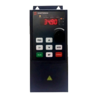
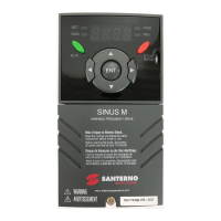
3.3 Button description of Keyboard
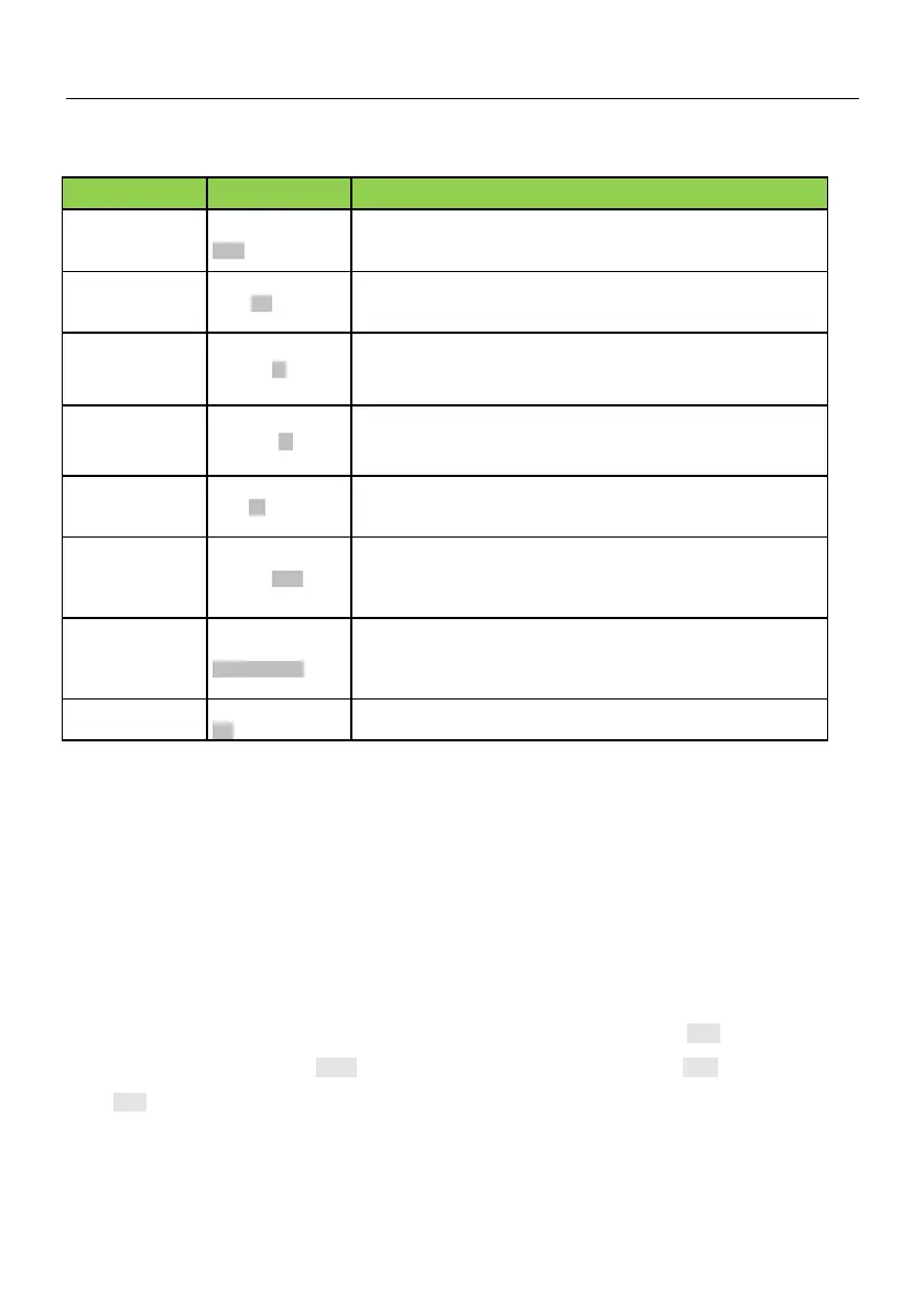
1、Switch between program and other states, which includes parameters
display and programming;
2、In menu status, press this key to return previous menu.
1、In program status, press this key to enter next menu.
2、In menu level 3, press this key to save parameters value.
1、In first level menu, increase function code PX according to edit bit
2、In second level menu, increase the function code PX YZ data.
3、In third level menu ,Increase the function code data
1、In first level menu, decrease function code PX according to edit bit
2、In second level menu, decrease the function PX YZ code data
3、In third level menu ,decrease the function code data
1、In third level menu ,use key >> to shift edit bit of the data
2、In stop/run status, switch the panel display parameters such as
frequency, current and voltage.
1、When running command is given via operation panel, the key is used to
control the start of inverter.
2、After setting the parameter auto tuning,start parameter auto tuning for
inverter start-up
Stop/Reset Key
STOP/RESET
1、When running command is given via operation panel, the key is used to
control the stop of inverter.
2、When the inverter has fault and has stopped, this key is used as
RESET key to clear the fault alarm.
0:Non function;1:forward point running.;2:reverse
3.4 Keypad Operating Status
3.4.1 Initialization after power on
When the power is switched on, panel will start 5 seconds’ initiation process. During this process, LED
displays "8.8.8.8.” , and all LED indicators on the panel are in ON stat
3.4.2 Stopping State
In stopping state, LED displays default parameters in flashing mode, and the unit indicator in right side
displays the unit of this parameters. In this state, all status indicators are OFF, press ►► key ,LED displays
fault code“n-xx”(xx=00-08), press SET key to enter and view the parameter; press PRG key to exit; and
press ►► key to scroll through parameters in stopping state.
3.4.3 Running state
In stopping state, after receiving running command, the drive enters running state. The LED and unit




 To Next Page