SINUS MINI High performance Vector Control Inverter User Manual
18
Digital output 1
(High-speed pulse
output)
(Optional)
Optical coupling isolation,dual polarity open collector output.
Output voltage range:0V to 24V Output current range:0mA
to 50mA
Contact driving capacity:AC250V,3A,COSø=0.4
485Positive signal of
differential signal
Rate:1200/2400/4800/9600/19200/38400
Up to 32 units at most, more than 32 units, use
repeaters.The longest distance 500m (shielded twisted pair
cable using standard) J6:485Terminal resistance selection:
ON is a 100 Omega terminal resistor,OFF is no terminal
resistance
485Negative side of
differential signal
485Shielding GND
of communication
Internal isolation from COM
NOTE:
﹡ If the user adjustable potentiometer in + 10V and GND, potentiometer resistance should not be less
than 5K Omega
2.8 Peripheral device selection of control circuit
+10V、AO1、485+、485−、DI2、DI4、
Y1、COM
Double glue
shielded cable
GND、AI1、AI2、DI1、DI3、DI5、+24V、
COM
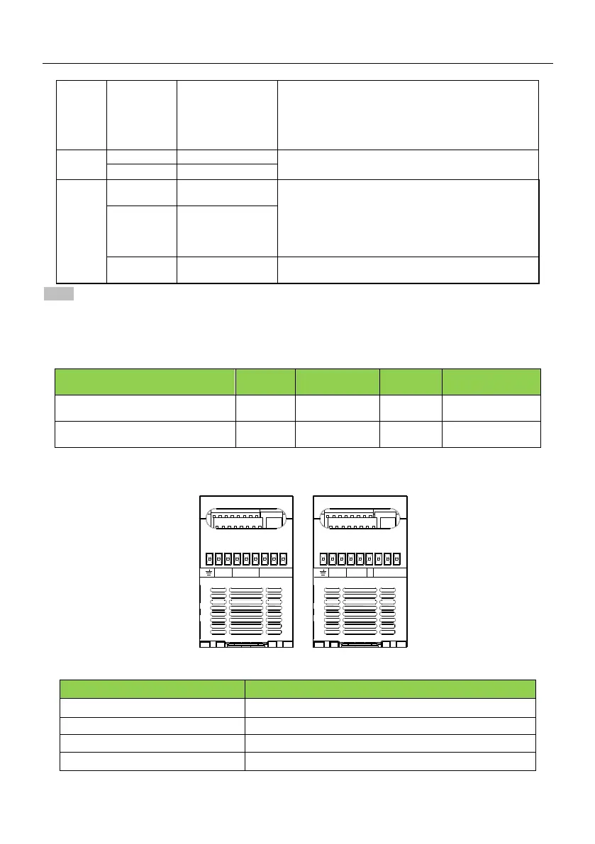
2.9 Function of main circuit terminal
E P B R S T U V W E P BL1
L2
U V W
OUTPUT
INPUT
BRAKE BRAKE
INPUT
OUTPUT
SINUS MINI−00xx 4T SINUS−00xx 2S
Terminal name and function description
Three (single) phase current input terminals
Braking resistor connecting terminal
Three phase AC output terminal