EasyManua.ls Logo

Santerno Sinus M User Manual

Santerno Sinus M
219 pages
To Next Page IconTo Next Page
Page #1 background imageLoading...
Page #1 background image
15P0073B1
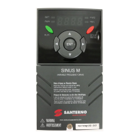
SINUS M
VARIABLE FREQUENCY DRIVE
USER MANUAL
-Installation and Programming
Instructions-
Issued on 17/02/11
R.03.1
SW Ver. EU2.3
Elettronica Santerno S.p.A.
Strada Statale Selice, 47 - 40026 Imola (BO) Italy
Tel. +39 0542 489711 - Fax +39 0542 489722
santerno.com sales@santerno.com
This manual is integrant and essential to the product. Carefully read the instructions contained herein as
they provide important hints for use and maintenance safety.
This device is to be used only for the purposes it has been designed to. Other uses should be considered
improper and dangerous. The manufacturer is not responsible for possible damages caused by improper,
erroneous and irrational uses.
Elettronica Santerno is responsible for the device in its original setting.
Any changes to the structure or operating cycle of the device must be performed or authorized by the
Engineering Department of Elettronica Santerno.
Elettronica Santerno assumes no responsibility for the consequences resulting by the use of non-original
spare-parts.
Elettronica Santerno reserves the right to make any technical changes to this manual and to the device
without prior notice. If printing errors or similar are detected, the corrections will be included in the new
releases of the manual.
Elettronica Santerno is responsible for the information contained in the original version of the Italian
manual.
The information contained herein is the property of Elettronica Santerno and cannot be reproduced.
Elettronica Santerno enforces its rights on the drawings and catalogues according to the law.
English

Table of Contents

Other manuals for Santerno Sinus M

Questions and Answers:

Santerno Sinus M Specifications

General IconGeneral
BrandSanterno
ModelSinus M
CategoryServo Drives
LanguageEnglish

Summary

USER MANUAL -Installation and Programming Instructions-

Important hints for use and maintenance safety

Manual is essential for product use. Read instructions for safe use and maintenance.

Manufacturer is not responsible for possible damages caused by improper, erroneous and irrational uses.

Manufacturer disclaims responsibility for damages from improper or irrational product use.

Elettronica Santerno is responsible for the device in its original setting.

Responsibility for the device in its original setting lies with Elettronica Santerno.

Any changes to the structure or operating cycle of the device must be performed or authorized by the Engineering Department of Elettronica Santerno.

Modifications to the device structure or cycle require authorization from the Engineering Department.

Elettronica Santerno assumes no responsibility for the consequences resulting by the use of non-original spare-parts.

No responsibility for consequences arising from the use of non-original spare parts.

Elettronica Santerno is responsible for the information contained in the original version of the Italian manual.

Responsibility for information is limited to the original Italian manual version.

The information contained herein is the property of Elettronica Santerno and cannot be reproduced.

Information is Elettronica Santerno's property; reproduction is prohibited.

SAFETY INSTRUCTIONS

Always follow safety instructions to prevent accidents and potential hazards from occurring.

Always adhere to safety instructions to prevent accidents and hazards.

In this manual, safety messages are classified as follows:

Safety messages in the manual are classified into WARNING and CAUTION.

Keep operating instructions handy for quick reference.

Keep operating instructions readily available for quick reference.

Read this manual carefully to maximize the performance of Sinus M series inverters and ensure safe usage.

Read the manual carefully for maximum performance and safe usage of Sinus M inverters.

Do not remove the inverter cover while power is applied or the unit is operating.

Never remove the inverter cover when power is applied or unit is operating to avoid electric shock.

Do not run the inverter with the front cover removed.

Do not operate the inverter with the front cover removed due to exposure to high voltage terminals.

Do not remove the cover except for periodic inspections or wiring, even if the input power is not applied.

Avoid cover removal unless for inspection/wiring, even when input power is off, to prevent electric shock.

SAFETY INSTRUCTIONS

Operate the switches with dry hands.

Always operate switches with dry hands to prevent electric shock.

Do not use the cable when its insulating tube is damaged.

Do not use damaged cables to prevent electric shock.

Do not subject the cables to scratches, excessive stress, heavy loads or pinching.

Protect cables from scratches, stress, loads, or pinching to prevent electric shock.

Install the inverter on a non-flammable surface. Do not place flammable material nearby.

Install inverter on non-flammable surface, away from flammable materials, to prevent fire.

Disconnect the input power if the inverter gets damaged.

Disconnect input power if inverter is damaged to prevent secondary accidents or fire.

After the input power is applied or removed, the inverter will remain hot for a couple of minutes.

Inverter remains hot for minutes after power application/removal, posing a burn risk.

Do not allow lint, paper, wood chips, dust, metallic chips or other foreign matter to enter the drive.

Prevent foreign matter entry into the drive to avoid fire or accidents.

OPERATING PRECAUTIONS

Handling and installation

Precautions for handling and installing the inverter.

Wiring

Instructions and precautions for wiring the inverter.

Trial run

Steps and precautions for performing a trial run of the inverter.

OPERATING PRECAUTIONS

Operation precautions

General precautions during inverter operation.

Fault prevention precautions

Measures to prevent faults and ensure safety.

Maintenance, inspection and parts replacement

Guidelines for maintaining, inspecting, and replacing inverter parts.

Disposal

Proper disposal procedures for the inverter.

General instructions

General guidelines for safe inverter operation and handling.

Important User Information

The purpose of this manual is to provide the user with the necessary information to install, program, start up and maintain the SINUS M series inverter.

Manual provides essential information for SINUS M series inverter installation, programming, startup, and maintenance.

This manual contains:

Overview of the manual's content structure and topics.

CHAPTER 1 - BASIC INFORMATION & PRECAUTIONS

1.1 Important precautions

Key precautions before handling the inverter.

Unpacking and inspection

Instructions for unpacking and inspecting the inverter.

CHAPTER 1 - BASIC INFORMATION & PRECAUTIONS

Preparations of instruments and parts required for operation

Prepare instruments and parts necessary for inverter operation.

Installation

Guidance on proper inverter installation for optimal performance and longevity.

Wiring

Instructions for connecting power supply, motor, and control signals.

1.2 Product Details

Appearance

Description and labeling of the inverter's external appearance.

Inside view after front cover is removed

Details of the inverter's internal components after removing the front cover.

1.3 Product assembling & disassembling

To remove the front cover: Lightly press both the indented sides of the cover and pull up.

Instructions for safely removing the inverter's front cover.

CHAPTER 2 - INSTALLATION

2.1 Installation precautions

Essential precautions for safe and correct inverter installation.

2.2 Dimensions

CHAPTER 3 - WIRING

3.1 Terminal wiring (Control I/Os)

Detailed wiring diagrams for control input/output terminals.

3.2 Power terminal block

3.2 Power terminal block

3.3 Control terminal block

3.4 PNP/NPN selection and connector for communication option

1. When using DC 24V inside inverter [NPN]

Configuration for NPN input using internal DC 24V.

2. When using external DC 24V [PNP]

Configuration for PNP input using external DC 24V.

3.5 Optional External Relay

CHAPTER 4 - BASIC CONFIGURATION

4.1 Connection of peripheral devices to the inverter

Guidance on connecting peripheral devices for proper inverter operation.

4.2 Recommended MCCBs and MCs

4.3 Recommended Fuses and Reactors

AC Reactors

DC Reactors

CHAPTER 5 - PROGRAMMING KEYPAD

5.1 Keypad features

Description of the keypad layout and its functions.

5.2 Alpha-numeric view on the LED keypad

5.3 Moving to other groups

Drive group

Basic parameters for inverter operation.

Function group 1

Basic parameters for output frequency and voltage adjustment.

Function group 2

Advanced parameters for PID operation and second motor.

I/O (Input/Output) group

Parameters for sequence setup using multi-function terminals.

Moving to other parameter groups is only available in the first code of each group as the figure shown below.

Navigation between parameter groups is limited to the first code of each group.

5.3 Moving to other groups

How to move to other groups at the 1st code of each group

Procedure to navigate parameter groups using the 1st code.

How to move to other groups from any codes other than the 1st code

Procedure to navigate parameter groups from codes other than the first code.

5.4 How to change the codes in a group

Code change in Drive group

Steps to change parameter codes within the Drive group.

Code jump

Method to jump between parameter codes within a group.

5.4 How to change the codes in a group

Navigating codes in a group

Procedure for navigating parameter codes within a group.

5.5 Parameter setting

Changing parameter values in Drive Group

Detailed steps for changing parameter values in the Drive Group.

5.5 Parameter setting

Frequency setting

Steps to set the run frequency in the Drive group.

5.5 Parameter setting

Changing parameter value in Input/Output group

Steps to change parameter values in the Input/Output group.

5.6 Monitoring of operation status

Output current display

How to monitor the output current in the Drive group.

5.6 Monitoring of operation status

Fault display

How to monitor fault conditions in the Drive group.

When more than one fault occurs at the same time

Information on displaying multiple faults occurring simultaneously.

5.6 Monitoring of operation status

Parameter initialize

Procedure to initialize parameters of all four groups.

CHAPTER 6 - BASIC OPERATION

6.1 Frequency Setting and Basic Operation

Guide to setting frequency and performing basic inverter operations.

6.1 Frequency Setting and Basic Operation

Frequency Setting via potentiometer & operating via terminals

Setting frequency using a potentiometer and operating via terminals.

6.1 Frequency Setting and Basic Operation

Frequency setting via potentiometer & operating via the Run key

Setting frequency via potentiometer and operating with the Run key.

CHAPTER 7 - FUNCTION LIST

7.1 Drive group

List of parameters and functions within the Drive group.

7.1 Drive group

7.1 Drive group

7.2 Function group 1

7.2 Function group 1

7.2 Function group 1

7.2 Function group 1

7.2 Function group 1

7.2 Function group 1

7.3 Function group 2

7.3 Function group 2

7.3 Function group 2

7.3 Function group 2

7.3 Function group 2

7.3 Function group 2

7.3 Function group 2

7.3 Function group 2

7.4 I/O group 2

7.4 I/O group 2

7.4 I/O group 2

7.4 I/O group 2

7.4 I/O group 2

7.4 I/O group 2

7.4 I/O group 2

CHAPTER 8 - CONTROL BLOCK DIAGRAM

8.1 Frequency and Drive mode setting

8.2 Accel/Decel setting and V/F control

CHAPTER 9 - BASIC FUNCTIONS

9.1 Frequency mode

Methods for setting frequency using keypad or analog inputs.

Keypad Frequency setting 1

Setting frequency using Keypad Frequency setting 1.

Keypad Frequency setting 2

Setting frequency using Keypad Frequency setting 2.

9.1 Frequency mode

Frequency setting via –10 ~ +10[V] input

Setting frequency using a -10 to +10V analog input.

9.1 Frequency mode

9.1 Frequency mode

Frequency setting via 0 ~ 10 [V] input or Terminal Potentiometer

Setting frequency using 0-10V input or a terminal potentiometer.

Frequency setting via 0 ~ 20 [mA] input

Setting frequency using a 0-20mA input.

9.1 Frequency mode

Frequency setting via –10 ~ +10[V] voltage input + 0 ~ 20[mA] input

Setting frequency using combined -10~+10V and 0-20mA inputs.

Frequency setting via 0 ~ 10[V] + 0 ~ 20[mA] input

Setting frequency using combined 0-10V and 0-20mA inputs.

9.1 Frequency mode

Frequency setting via RS 485 communication

Setting frequency using RS485 communication.

Frequency setting via Digital Volume (up-down)

Setting frequency using digital up-down controls.

Analog Hold

Functionality to hold analog frequency input.

9.2 Multi-Step Frequency setting

9.3 Operating command setting method

Operation via keypad RUN key and STOP/RST key (Modality 0)

Operating the inverter using keypad RUN/STOP keys.

Operating command via FX, RX terminal (Modality 1)

Operating the inverter using FX/RX terminals.

9.3 Operating command setting method

Operating command via FX, RX terminal (Modality 2)

Operating the inverter using FX/RX terminals in Modality 2.

Operating command via RS485 communication (Modality 3)

Operating the inverter via RS485 communication.

9.3 Operating command setting method

Rotating direction selection via –10 ~ +10[V] input of V1 terminal

Selecting motor rotation direction using V1 terminal input.

FX/RX Run Disable

Disabling FX/RX run commands.

9.3 Operating command setting method

Power On Start select

Configuring automatic start upon power application.

Restart after fault reset

Configuring automatic restart after a fault is cleared.

9.4 Accel/Decel time and pattern setting

Accel/Decel time setting based on Max frequency

Setting Accel/Decel times based on maximum frequency.

9.4 Accel/Decel time and pattern setting

Accel/Decel time setting based on Operating Frequency

Setting Accel/Decel times based on operating frequency.

9.4 Accel/Decel time and pattern setting

Multi-Accel/Decel time setting via Multi-function terminals

Setting multiple Accel/Decel times using multi-function terminals.

9.4 Accel/Decel time and pattern setting

Accel/Decel pattern setting

Configuring Accel/Decel patterns (Linear, S-curve).

9.4 Accel/Decel time and pattern setting

Accel/Decel Disable

Function to disable Accel/Decel settings.

9.5 V/F control

Linear V/F pattern operation

Using Linear V/F pattern for constant torque applications.

Square V/F pattern

Using Square V/F pattern for fan and pump applications.

9.5 V/F control

User V/F pattern operation

Adjusting Volt/Frequency ratio for special motors and loads.

Output voltage adjustment

Adjusting output voltage for motors with lower rated voltage.

9.5 V/F control

Manual torque boost

Setting manual torque boost for forward/reverse directions.

Auto torque boost

Inverter automatically calculates torque boost using motor parameters.

9.6 Stop method select

Decel to stop

Configuring the inverter to stop by controlled deceleration.

DC braking to stop

Configuring the inverter to stop using DC braking.

Coast to stop

Configuring the inverter to stop by coasting.

9.7 Frequency limit

Frequency limit using Max Frequency and Start Frequency

Setting frequency limits using Max and Start frequencies.

Frequency command limit using High/Low limit

Setting frequency limits using High/Low limit selection.

9.7 Frequency limit

Skip frequency

Parameters to skip resonant frequencies during acceleration/deceleration.

CHAPTER 10 - ADVANCED FUNCTIONS

10.1 DC brake

Functions related to DC braking for stopping the motor.

DC brake at stop

Configuration for DC braking when stopping the motor.

10.1 DC brake

DC brake at start

Configuration for DC braking when starting the motor.

DC brake hold

Functionality for holding DC brake.

10.2 Jog operation

10.2 Jog operation

Terminal JOG FX/RX operation

Performing Jog operation using terminals FX/RX.

10.3 UP-DOWN

Up-down storage function

Functionality to save and initialize up-down frequency settings.

10.3 UP-DOWN

Up-down mode select

Selecting the mode for up-down frequency adjustment.

10.3 UP-DOWN

10.4 3-Wire operation (Start – Stop via push buttons)

10.5 Dwell operation

10.6 Slip compensation

10.6 Slip compensation

10.7 PID control

10.7 PID control

Normal PID block diagram (H54=0)

Process PID block diagram (H54=1)

10.7.1 PID reference

10.7.1 PID reference

10.7.2 PID feedback

10.7.2 PID feedback

10.7.3 PID Limit

10.7.4 Inverse PID

Functionality for inverse PID control to stabilize systems.

10.7.5 Sleep & Wake up functionality

Features for sleep and wake-up operations based on PID settings.

10.7.5 Sleep & Wake up functionality

10.7.6 Open Loop1 (Addtional)

10.7.7 Open Loop1 Source

10.7.8 Accel/Decel Change frequency

10.8 Auto-tuning

10.9 Sensorless Vector Control

10.10 Energy-saving operation

10.11 Speed search

10.11 Speed search

10.12 Auto restart try

10.13 Operating sound select (Carrier frequency change)

10.14 2nd motor operation

10.14 2nd motor operation

10.15 Self-Diagnostics function

10.15 Self-Diagnostics function

10.16 Frequency setting and 2nd drive method select

10.16 Frequency setting and 2nd drive method select

10.17 Over voltage trip prevention deceleration and Power Braking

10.18 External brake control

10.19 Kinetic energy buffering

10.20 DRAW Control

10.20 DRAW Control

10.21 2 Phase PWM

10.22 Cooling fan control

10.23 Operating mode selection when cooling fan trip occurs

10.24 Parameter read/write

10.25 Parameters Restore default / Lock

Parameters restore

Procedure for restoring inverter parameters to factory default settings.

Password register

Registering a password for parameter lock.

10.25 Parameters Restore default / Lock

Parameter Lock

Locking and unlocking user-set parameters using a password.

10.25 Parameters Restore default / Lock

10.26 Functions related to “Fire Mode”

10.26 Functions related to “Fire Mode”

CHAPTER 11 - MONITORING

11.1 Operating status monitoring

Monitoring of inverter operating status parameters.

Output current

How to monitor the inverter's output current.

Motor RPM

How to monitor the motor's RPM.

Inverter DC Link Voltage

How to monitor the inverter's DC Link Voltage.

11.1 Operating status monitoring

User display select

Selecting items to display in User display (vOL).

11.1 Operating status monitoring

Power on display

Selecting the parameter displayed on keypad after Power ON.

11.2 Monitoring the I/O terminal

Input terminal status monitoring

Monitoring the status (ON/Off) of the input terminals.

Output terminal status monitoring

Monitoring the status (ON/Off) of the output terminals (MO, relays).

11.3 Monitoring fault condition

Monitoring current fault status

Monitoring the current fault status and operating status at fault.

Fault History Monitoring

Monitoring and resetting stored fault history.

11.3 Monitoring fault condition

11.4 Analog Output

11.5 Multi-function output terminal (MO) and Relay (3AC)

11.5 Multi-function output terminal (MO) and Relay (3AC)

11.5 Multi-function output terminal (MO) and Relay (3AC)

11.5 Multi-function output terminal (MO) and Relay (3AC)

11.5 Multi-function output terminal (MO) and Relay (3AC)

11.5.1 A, B Contact selection

11.5.2 A, B Contact On/Off delay

11.6 Output terminal select at keypad-inverter communication error

CHAPTER 12 - PROTECTIVE FUNCTIONS

12.1 Electronic Thermal Protection

Protection against motor overheating using electronic thermal monitoring.

12.2 Overload Warning and trip

Overload warning

Warning triggered when current exceeds overload level.

12.2 Overload Warning and trip

Overload trip

Trip occurs when current exceeds overload level for a set time.

12.3 Stall prevention

12.3 Stall prevention

12.4 Input/Output phase loss protection

12.5 External trip signal

12.6 Inverter Overload

12.7 Frequency command loss

12.7 Frequency command loss

12.8 DB Resistor Enable Duty setting

CHAPTER 13 - RS485 COMMUNICATION

13.1 Introduction

Overview of RS485 communication for inverter control and monitoring.

13.1.1 Features

Key features of RS485 communication interface for factory automation.

13.1.2 Before installation

Important safety warning before installing RS485 communication.

13.2 Specification

13.2.1 Performance specification

Technical performance specifications for RS485 communication.

13.2.2 Hardware specification

Hardware specifications for RS485 communication setup.

13.2.3 Communication specification

Communication protocol specifications for RS485.

13.3 Installation

13.3.1 Connecting the communication line

Steps for connecting the RS485 communication line to the inverter.

13.5 Communication protocol (MODBUS-RTU)

13.6 Communication protocol (ES BUS)

13.6.1 Basic format

Basic message format for ES BUS communication protocol.

13.6 Communication protocol (ES BUS)

CMD: Capital letter

List of capital letter commands and their ASCII-HEX values.

Data: ASCII-HEX

Explanation of data format using ASCII-HEX.

Ex) Command Message (Request) for reading one address from address “3000”

Example of a command message for reading a specific address.

13.6.2 Detail communication protocol

1.1) Acknowledge Response:

Format for acknowledge response to read requests.

1.2) Negative Acknowledge Response:

Format for negative acknowledge response to read requests.

13.6.2 Detail communication protocol

2) Request for Write:

Format for requesting write of data.

2.1) Acknowledge response:

Format for acknowledge response to write requests.

2.2) Negative response:

Format for negative acknowledge response to write requests.

3) Request for Monitor Register

Request format for monitoring registers.

3.1) Acknowledge Response:

Acknowledge response format for monitor register requests.

3.2) Negative Acknowledge Response:

Negative acknowledge response for monitor register requests.

13.7 Parameter code list <Common area>

13.7 Parameter code list <Common area>

13.7 Parameter code list <Common area>

CHAPTER 14 - TROUBLESHOOTING & MAINTENANCE

14.1 Protective functions

List of protective functions and their fault displays.

Fault Display and information

Information on fault types and operating status at the time of fault.

14.1 Protective functions

Fault Display and Information

Descriptions of fault codes displayed on the keypad.

14.1 Protective functions

Fault remedy

Troubleshooting steps and remedies for various inverter faults.

Overload Protection

Explanation of Overload (OLT) and Inverter Overload (IOLT) protection.

14.2 Fault remedy

14.2 Fault remedy

Fault remedy

Troubleshooting steps for specific protective functions and causes.

14.3 Precautions for maintenance and inspection

Daily inspections

Routine checks for inverter installation environment and condition.

Periodic inspection

Regular checks for loose parts, cooling system, and components.

14.4 Check points

14.5 Part replacement

CHAPTER 15 - SPECIFICATIONS

Input & output ratings: 200-230V

Electrical and performance ratings for 200-230V models.

Input & output ratings: 380-480V

Specifications (Continued)

Control

Control methods, frequency settings, and V/F patterns.

Operation

Operation modes, frequency settings, and I/O features.

Input

Details of input terminals and their functions.

Output

Details of output terminals and their functions.

Specifications (Continued)

Protective function

List of protective functions like Over Voltage, Over Current, etc.

Environment

Environmental operating conditions for the inverter.

15.1 Temperature Derating Information

15.2 Inverter Efficiency and Heating Loss

CHAPTER 16 - OPTIONS

16.1 Remote option

Information on the remote keypad and cable options.

Remote Keypad

Description and diagram of the remote keypad.

Remote Cable (2M,3M,5M)

Details of available remote cable lengths and models.

16.1 Remote option

Installation

Step-by-step instructions for installing the remote keypad.

16.1 Remote option

16.2 Conduit Kit

Installation

Instructions for installing conduit kits for different Sinus M models.

16.2 Conduit Kit

Conduit kit

Catalog of available conduit kits for Sinus M inverters.

16.3 EMC Filters

RECOMMENDED INSTALLATION INSTRUCTIONS

Instructions for installing EMC filters to meet EMC directives.

16.3 EMC Filters

Output ferrite ring

16.4 Braking resistors

16.4.1 Dimensions

16.4.1 Dimensions

16.4.1 Dimensions

16.4.2 Braking resistor wiring diagram

CHAPTER 17 - EC Declaration of Conformity