7-1
CHAPTER 7 - FUNCTION LIST
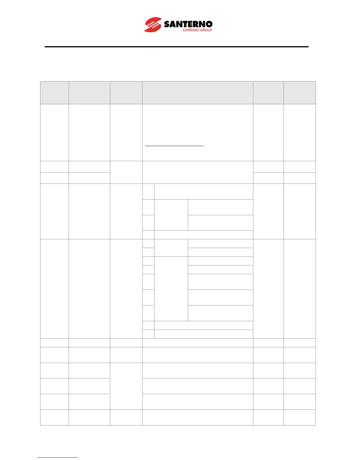
7.1 Drive group
LED
display
Parameter
name
Setting
range
Description
Factory
defaults
Adj.
during
This parameter sets the frequency that
the inverter is commanded to output.
During Stop: Frequency Command
During Run: Output Frequency
During Multi-step operation:
Multi-step frequency 0.
It cannot be set greater than F21- [Max
During Multi-Accel/Decel operation, this
parameter serves as Accel/Decel time
Run/Stop via Run/Stop key on the
keypad
FX: Motor forward run
RX: Motor reverse run
FX: Run/Stop enable
RX: Direction
Terminal V1 setting 1
+ Terminal I
Terminal V1 setting 2+
Terminal I
- Displays PID Feedback - -
Sets Multi-Step frequency 1 during
Multi-step operation.
Sets Multi-Step frequency 2 during
Multi-step operation.
Sets Multi-Step frequency 3 during
Multi-step operation.
Displays the output current to the
motor.