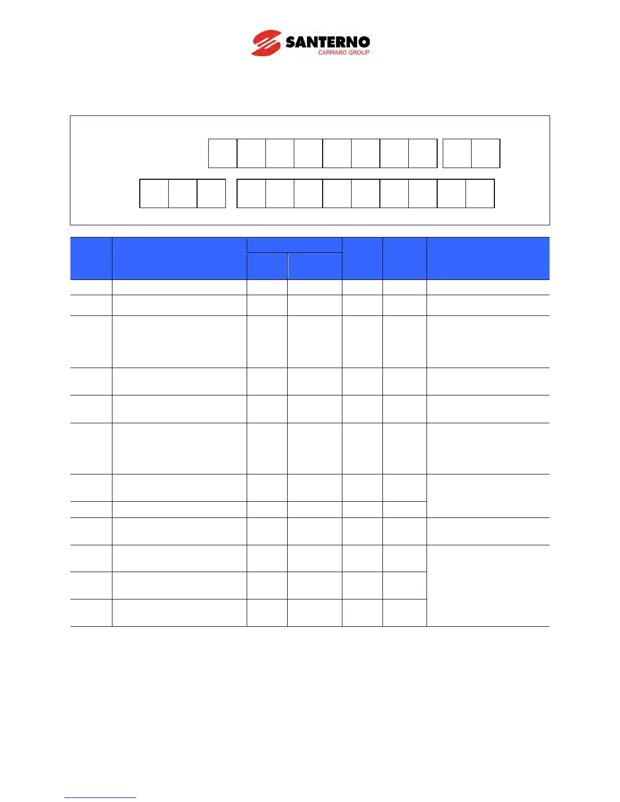
3.3 Control terminal block
Screw
size
Torque
[Nm]
Specification
Multi-function input T/M 1-8
Power supply for external
Input terminal for Voltage
operation
Max input voltage:
–12V ~ +12V input
Input terminal for Current
0 ~ 20mA input
Internal resistor: 250
11[V]
Max output current:
Multi-function terminal for
open collector
24V External Power
Supply
Max output current:
100mA
Multi-function relay output
A contact NO
Below 250V AC, 1A
Below 30V DC, 1A
Multi-function relay output
B contact NC
Common for Multi-function
relays
Note 1) Tie the control wires more than 15cm away from the control terminals. Otherwise, it interferes
with front cover reinstallation.
Note 2) Use Copper wires rated 600V, 75°C and higher.
Note 3) Use the recommended tightening torque when securing terminal screws.
Note 4) When you use external power supply (24V) for multi-function input terminal (P1~P8),
terminals will be active above 12V level. Take caution not to drop the voltage below 12V.