10.16 Frequency setting and 2
nd
drive method select
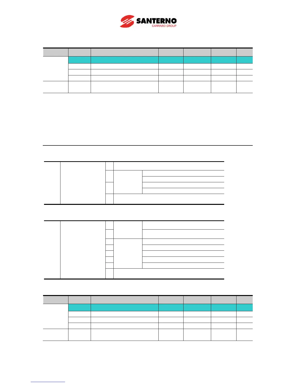
Group Display Parameter Name Setting Range Default Unit
Drive
group
drv Drive mode 1 - 0 ~ 3 1 -
I17~I24
Multi-function input
Drive mode 1 is used when the input set as 2nd source is not entered into multi-
(I17~I24)
When setting a multifunction digital input as a second source (22), Drive Mode 2 can
set the frequency value and send commands. This is used when communication is
suspended and local operating mode is resumed.
The switching method for Drive mode 1 and Drive mode 2 is as follows: if multi-input
terminal set as Drive mode 2 is off, it used as Drive mode 1; If multi-input terminal set
as Drive mode 2 is on, it used as Drive mode2.
Selects the self drive in the 2
nd
switching of drv2 among the followings
0 Operation via Run/Stop key on the Keypad
1
RX: Forward/Reverse command
3 Operation via communication
Selects the self drive in the 2
nd
switching of Frq2 among the following:
2
0
Digital
Keypad digital frequency mode1
1 Keypad digital frequency mode2
V1 terminal setting1: –10 ~ +10V
V1 terminal setting2: 0 ~ +10V
V1 terminal setting1 + I terminal
V1 terminal setting2 + I terminal
7 Setting via RS-485 communication
The following is an example for switching of drv1 and drv2.
Group Display Parameter Name Setting Range Default Unit
Drive
group
drv Drive mode 1 - 0 ~ 3 1 -
Multi-function input
terminal P8 input terminal
-
0 ~ 29 7
The following figure is drawn when setting is like the above and command frequency is 30
[Hz], F4 [stop method]=0.