Frequency setting via 0 ~ 10 [V] input or Terminal Potentiometer
Group Code Parameter Name Setting Range Initial Unit
Drive group 0.00 [Frequency Command] - 0 ~400 0.00 Hz
Frq [Frequency Mode] 3
0 ~ 8 0
I/O group I6
[Filter time constant for V1
input]
[Frequency corresponding
to I7]
[Frequency corresponding
to I9]
Select 3 in Frq code of Drive group.
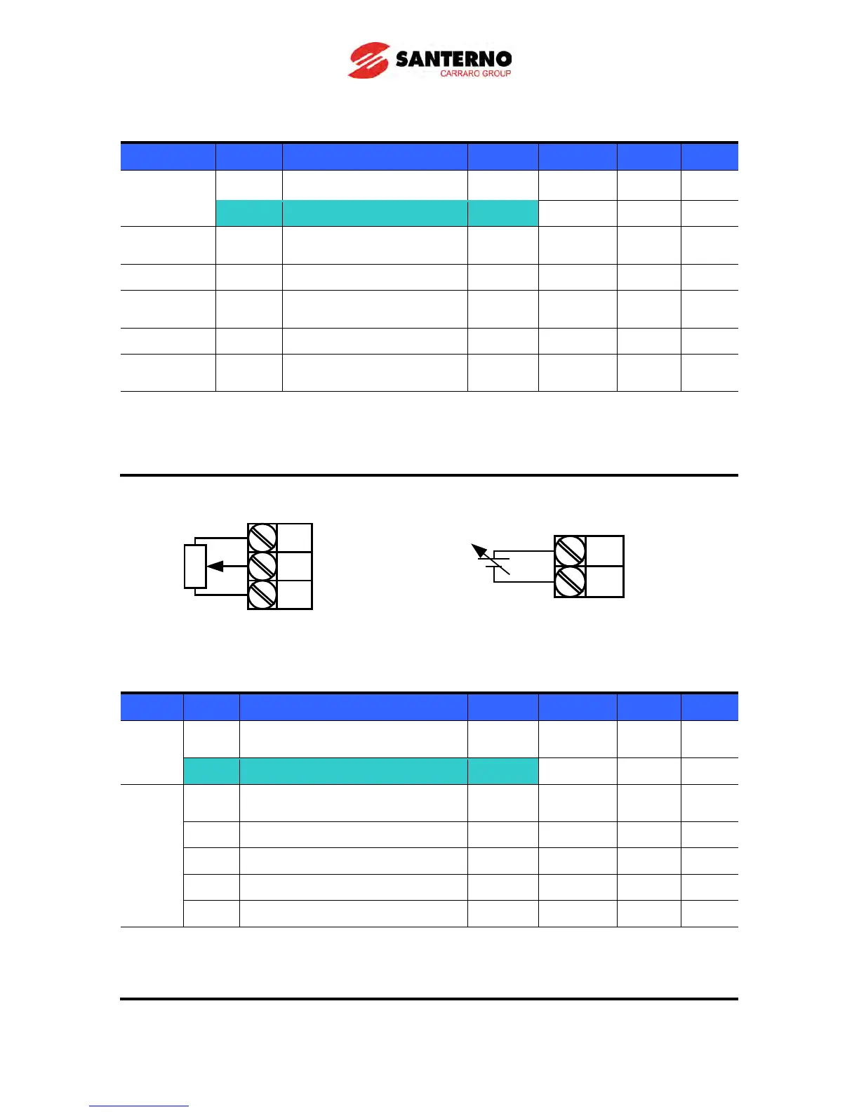
0-10V can be directly applied from an external controller or a potentiometer connected on
terminals VR, V1 and CM.
Wire the terminals as shown below and refer to page 9-3 for I6 ~ I10.
Frequency setting via 0 ~ 20 [mA] input
Group Code Parameter Name Setting Range Initial Unit
Drive
0.00 [Frequency Command] - 0 ~400 0.00 Hz
Frq [Frequency Mode] 4
0 ~ 8 0
[Filter time constant for I input]
[I input minimum current]
[Frequency corresponding to I12]
[Frequency corresponding to I14]
Select 4 in Frq code of Drive group.
Frequency is set via 0~20mA input between I and CM terminal.
VR
V1
CM
Wiring of potentiometer
V1
CM
0 ~ 10V input via external controller