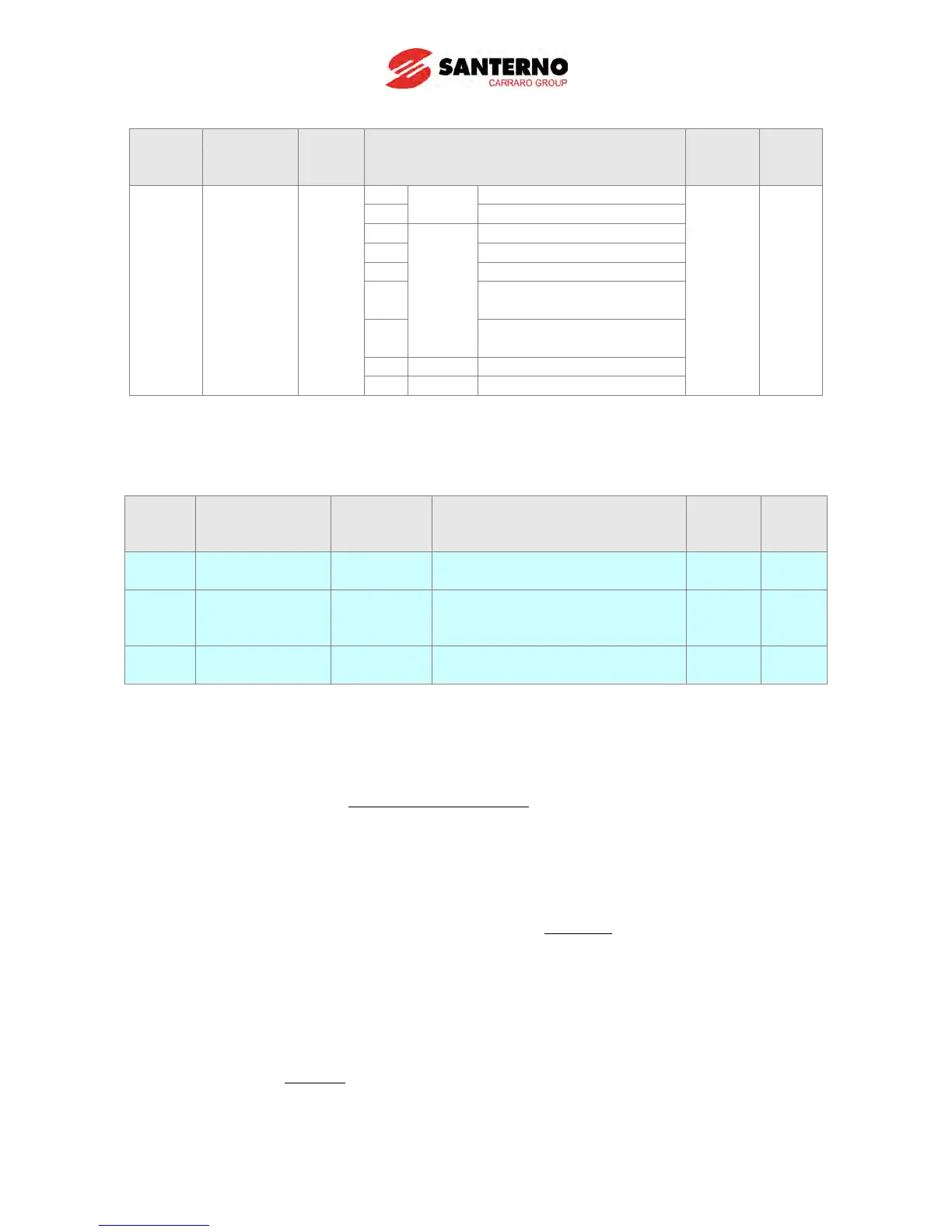
LED
display
Parameter
name
Setting
Range
Description
Factory
defaults
Frq
Frequency
setting
method
0 ~ 7
Terminal V1 setting 1+
Terminal I
Terminal V1 setting 2+
Terminal I
- The PID reference source can be selected in H57 code of function group2.
- The PID REF value can be changed and checked in the “rEF” of DRV group.
- PID value is basically created in ‘Hz’. ‘Hz’ is not a physical unit, so the internal PID reference is
calculated as a ‘%’ of Maximum frequency (F21).
LED
display
Parameter
name
Setting
Range
Description
Factory
defaults
PID control standard value
setting
0.0~100.0
Minimum Feedback Scaling
factor
0.0 O
I90
Maximum Feedback Scaling
factor
100.0 O
- “REF” code of drive group is the additional function code of this version for real unit and the
display only code. Refer to the equation below.
min)(89)(
min)(89max)(90
reference physical Real UnitIHzcePIDreferen
FrequencyMax
UnitIUnitI
+×
−
=
- If you want to display the real physical reference with %, set each I89 and I90 to 0.0 and 100.0
(Factory default). If the set value of F21 and the PID command are each 50Hz and 20Hz
respectively, then the PID reference should be like this:
04000020
050
000100
...
.
..
=+×
−
.
- You can display the physical value with Bar. For example, the pressure sensor has minimum
output 0V when 1.0 Bar and 10V when 20.0 bars. In this case, I89 and I90 should be set to 1.0
and 20.0 respectively.
- If the max frequency and the PID command are 50Hz and 20Hz each, then the PID reference
should be like this.
6801020
050
01020
...
.
..
=+×
−