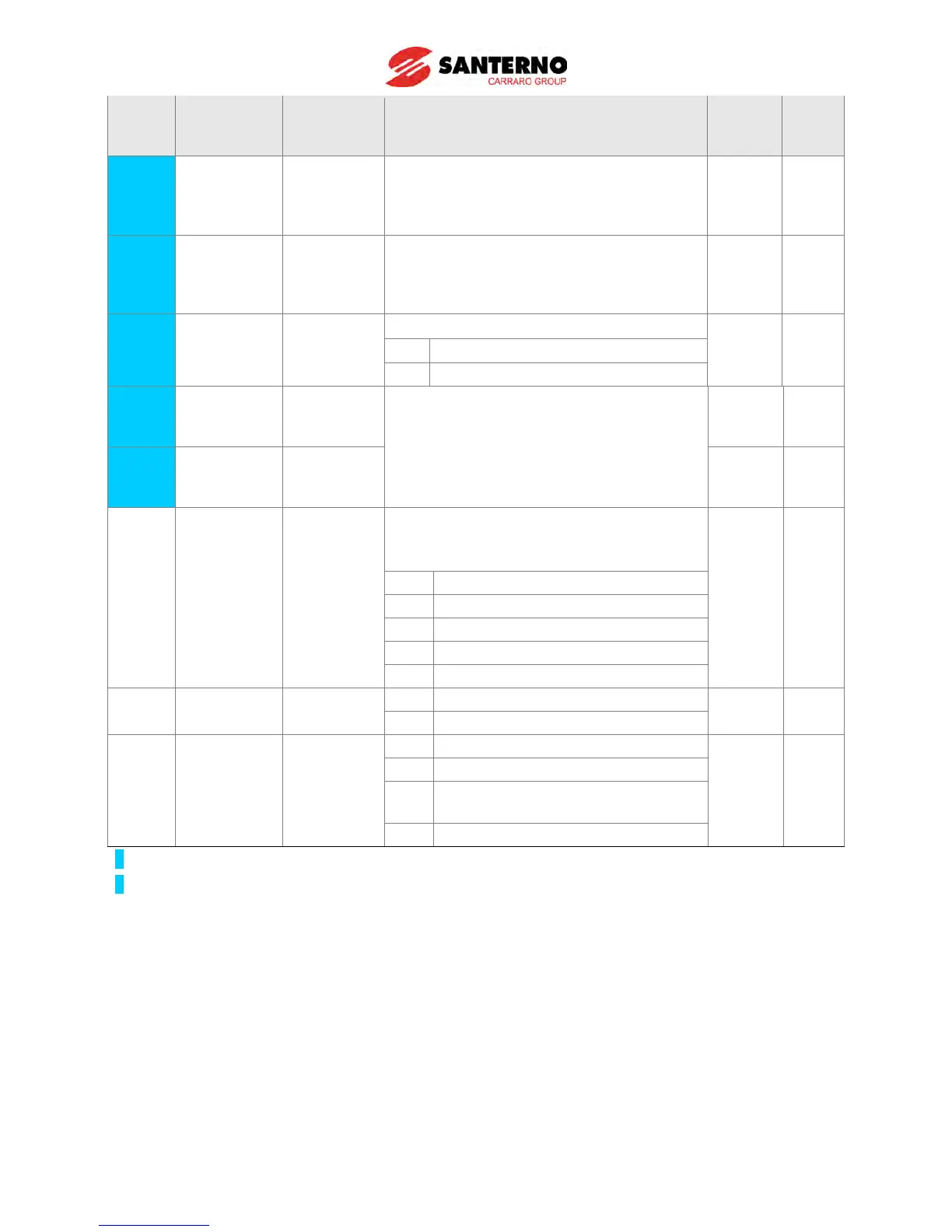
EasyManua.ls Logo

Santerno Sinus M - 7.3 Function group 2

Santerno Sinus M
219 pages
Print Icon
To Next Page IconTo Next Page
To Previous Page IconTo Previous Page
Loading...
7-14
LED
display
Parameter
name
Min/Max
range
Description
Factory
defaults
Adj.
during
run
H52
2)
[Integral
time for PID
controller
(I gain)]
0.1~32.0
[sec]
1.0
O
H53
2)
[Differential
time for PID
controller (D
gain)]
0 ~ 30.0
[sec]
0.0
O
H54
2)
[PID control
mode
select]]
0 ~ 1
Selects PID control mode
0
X
0 Normal PID control
1
Process PID control
H55
2)
[PID output
frequency
high limit]
0.1~400[Hz]
This parameter limits the amount of the
output frequency through the PID control.
The value is settable within the range of
F21 [Max frequency] and F23 [Start
frequency].
50.00
O
H56
2)
[PID output
frequency
low limit]
0.1~400[Hz]
0.50
O
H57
[PID
reference
source
select]
0~4
Selects PID reference source.
Reference is indicated in “rEF” of Drive
group.
0
X
0
Keypad digital setting 1
1
Keypad digital setting 2
2
V1 terminal setting 2: 0~10V
3
I terminal setting: 0~20mA
4
Setting as RS-485 communication
H59 Inverse PID 0 ~ 1
0
Normal
0 X
1
Inverse
H60
[Self-
diagnostic
select]
0 ~ 3
0
Self-diagnostic disabled
0
X
1
IGBT fault/Ground fault
2
Output phase short & open/ Ground
fault
3
Ground fault
1)
: Set H40 to 3 (Sensorless vector control) to display this parameter.
2)
: Set H40 to 2 (PID control) to display this parameter.

Table of Contents

Other manuals for Santerno Sinus M