SINUS MINI High performance Vector Control Inverter User Manual
17
2.7 Control circuit terminal function
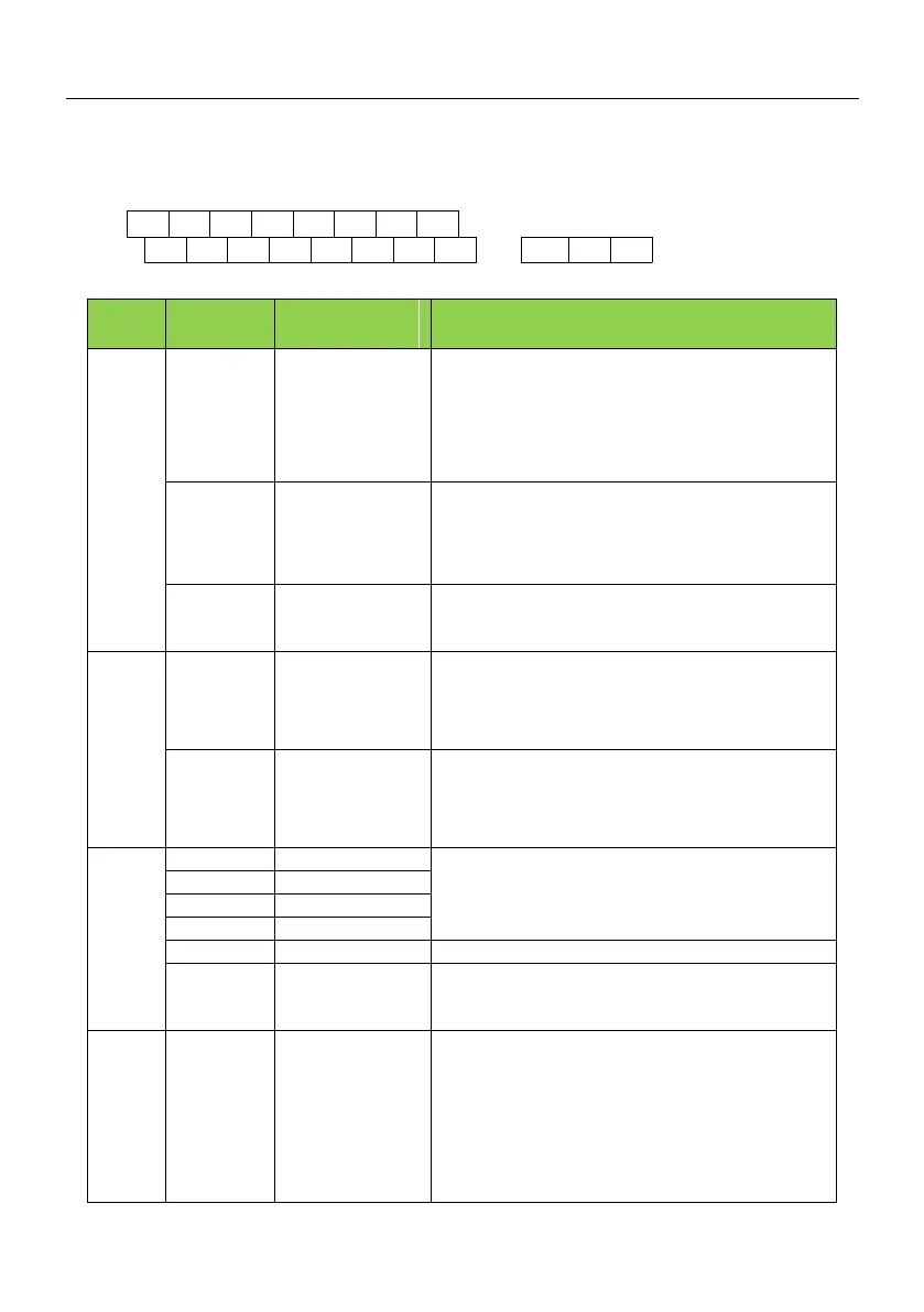
2.7.1 Control loop terminal line
GND AI1 AI2 DI1 DI3 DI5 +24VCOM
+10V
AO1
485+
485-
COM
RA1 RB1 RC1
Y1
DI4
DI2
2.7.2 Control circuit terminal instruction
External terminal of
10V power supply
Provide +10V power supply for external units, with maximum
output current of 10mA.
It is generally used as the operating power supply for the
external potentiometer.
The potentiometer resistance range is 1kΩ to 5kΩ.
External terminal of
24V power supply
Provide +24V power supply for external units. It is generally
used as the operating power supply for digital input/output
terminal and the external sensor.
Maximum output current: 200mA
External power input
terminals
When using external signal to drive DI1~DI5,OP should be
connected to external power supply,The factory defaults (J7)
to the 24V connection
1. Input voltage range: DC 0V ~ 10V /4mA ~ 20mA, chosen
by jumper J4 on control board.
2. Input impedance: 22kΩ of voltage input, 500Ω of current
input.
1.Input range:DC 0V~10V/4mA~20mA,chosen by jumper
J5 on control board
2.Input impedance: 22kΩ of voltage input, 500Ω of current
input.
1. Optical coupling isolation,bipolar input.
2. Input impedance:4.7kΩ.
3. Electrical level input range:9V~30V.
High-speed pulse
input terminal
(Optional)
DI5 can be used as high-speed pulse input channel.
Maximum input frequency:100kHz.
The voltage or current output is determined by jumper J3 on
the control panel.
Output voltage range: 0V to 10V Output current range:0mA
to 20mA.