−35−
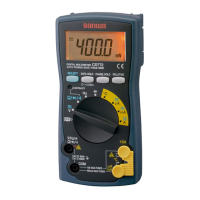
5-4 Testing Diode ( )
Never apply voltage to the input terminals.
WARNING
5-3 Resistance Measurement (1)
Never apply voltage to the input terminals.
WARNING
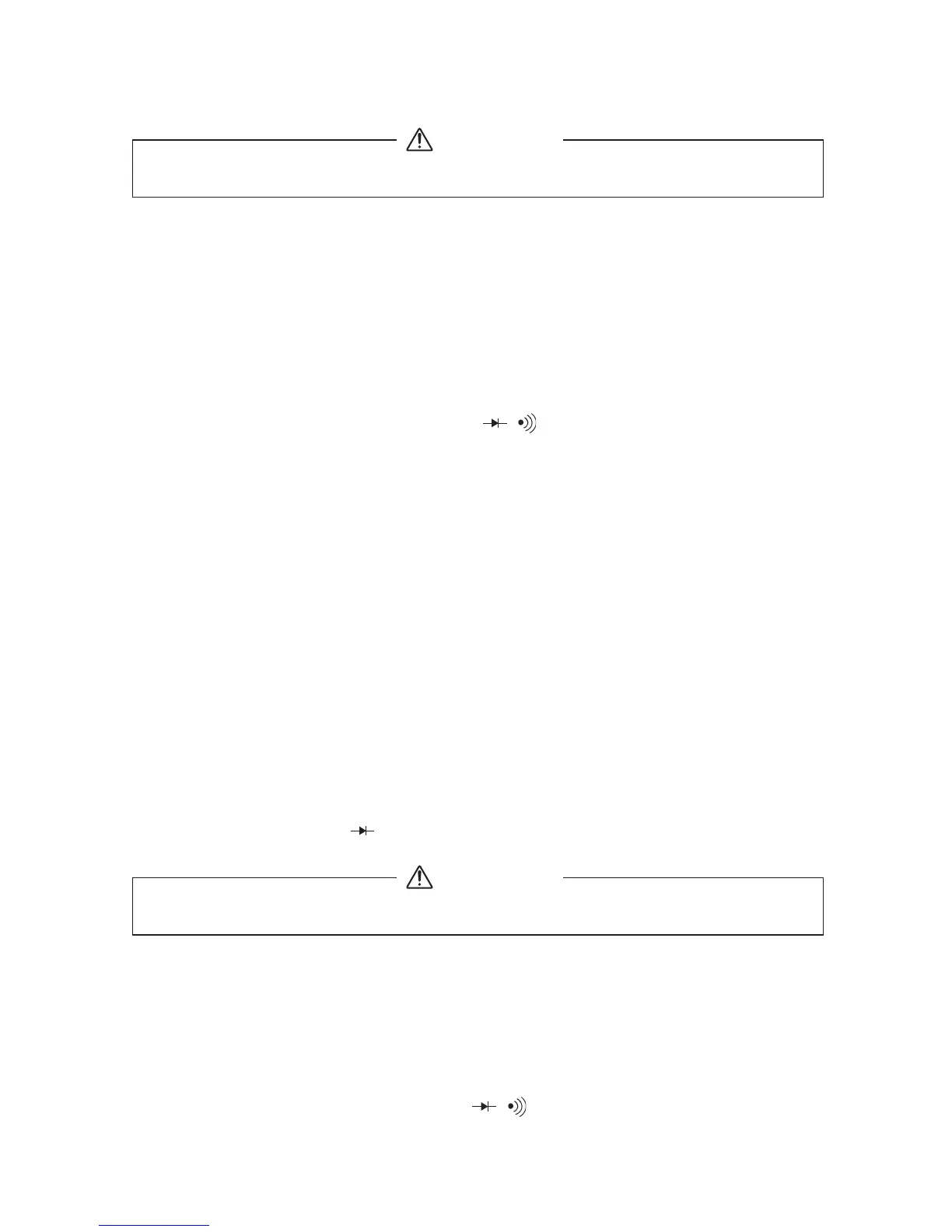
1) Application
Resistance of resistors and circuits are measured.
2) Measuring ranges
4001〜40 M1 (6 ranges)
3) Measurement procedure (See Fig 7, page 10)
①Connect the black plug of the test lead to the COM − input
terminal and the red plug to the + input terminal.
②Set the function switch at "1/ / " function.
③Select the select switch at "1" (M1).
④Apply the black and red test pin to measured circuit.
⑤Read the value on the display.
⑥After measurement, remove the red and black test pins from the
circuit measured.
⑦Turn the function switch to the position of OFF.
●If measurement is likely to be influenced by noise, shield the object
to measure with negative potential (test lead black).
●If a test pin is touched by a finger during measurement, measurement
will be influenced by the resistance in the human body to result in
measurement error.
●The input terminals release voltage is about 0.4 V.
1) Application
The quality of diodes is tested.
2) Measurement procedure (See Fig 8, page 11)
①Connect the black plug of the test lead to the COM − input
terminal and the red plug to the + input terminal.
②Set the function switch at "1/ / " function.