13
3-3 Construction of digital multimeter
Now let us see how a digital multimeter converts an analog quantity into a digital one (A/D
conversion) to display a numeric value.
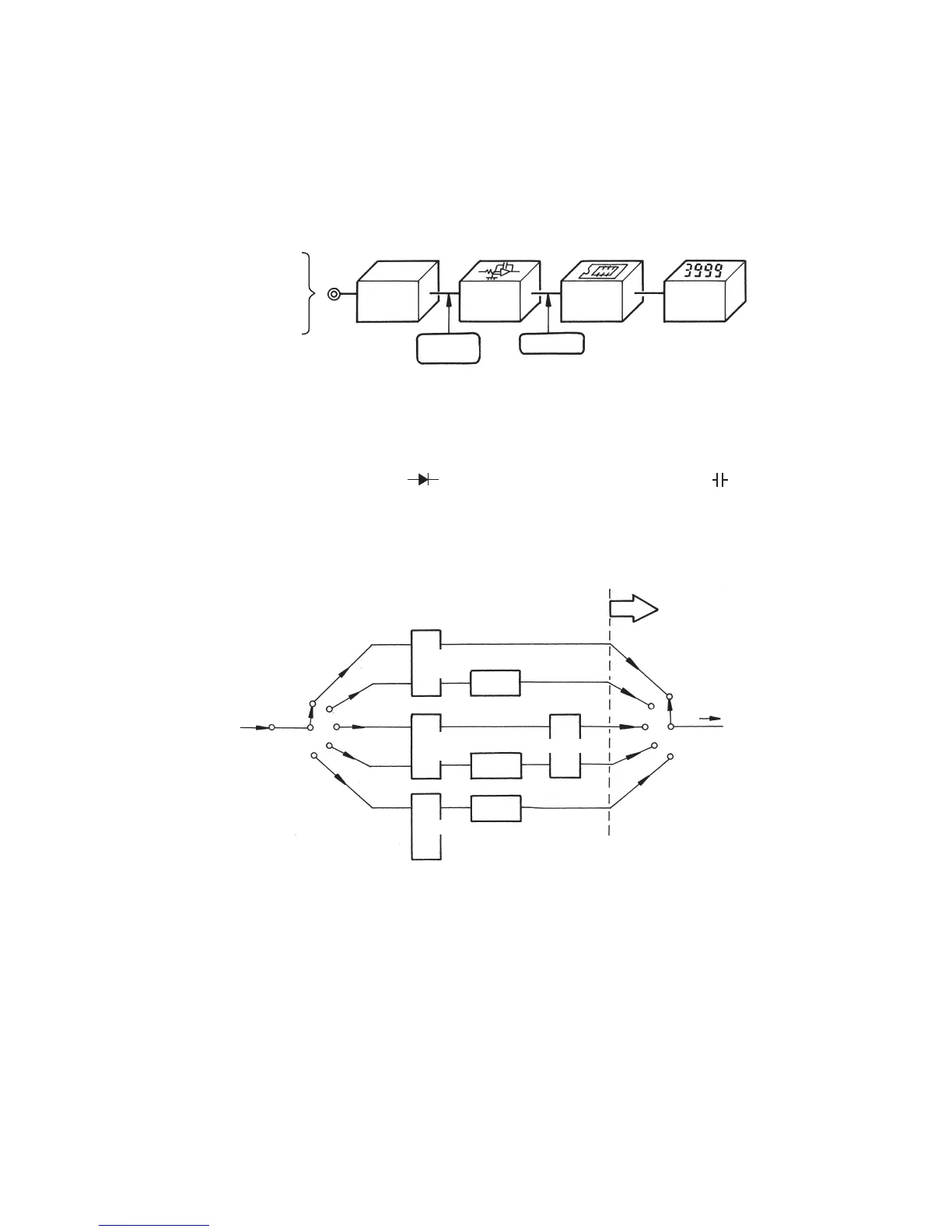
The circuits of a digital multimeter are roughly divided into five blocks of an input signal conversion
section, an A/D conversion section, a logic circuit, and a readout.
A digital multimeter generally allows for measuring 5 kinds of electric quantities: DC voltage (DCV),
AC voltage (ACV), DC current (DCA), AC current (ACA), and resistance (Ω). The PC20TK also
allows for performing a diode test (
) and measuring electric capacitance (
). Each kind of
electric quantities (input signals) is selected using the Function switch, all converted into DC
voltage signals of less than several 100 mV through a voltage divider, an electric shunt, an AC/DC
converter (rectifier), or the like, and then added to the input connector of the analog-digital
converter.
Fig. 3-2: Block diagram of digital multimeter
Fig. 3-3: Input signal conversion section
DC voltage
(analog quantity)
Input signal
conversion
section
A/D
conversion
section
Logic circuit Readout
Digital output
Measured quantity
DCV
DCA
ACV
ACA
Ω
Further information on each item will be given below:
Input
DC voltage (DCV)
DC current (DCA)
AC voltage
(ACV)
AC current
(ACA)
Resistance (Ω)
Voltage
divider
All is converted into
DC voltage (analog
quantities)
To A/D conversion
section
AC/DC
conversion
AC/DC
conversion
R/V
conversion
Electric
shunt
I/V conversion
Comparator