24
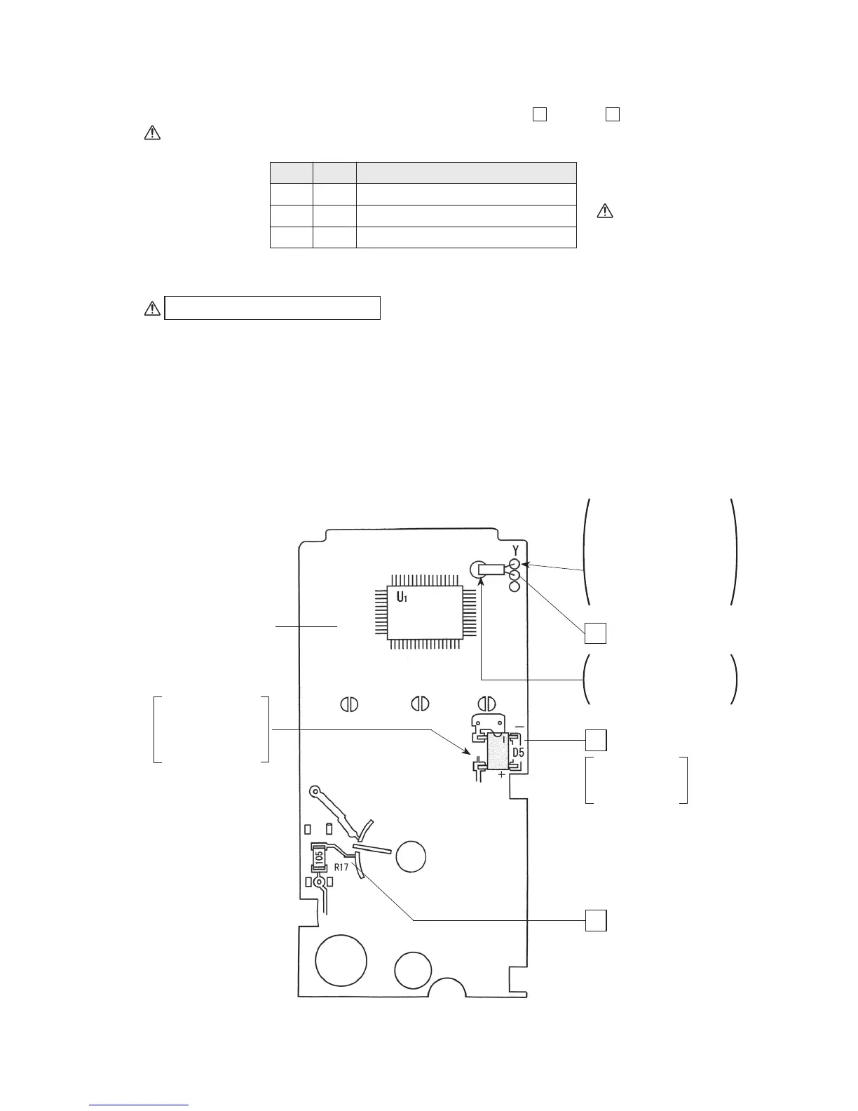
4-6 Mounting and wiring components to printed circuit board (large)
1. Mounting components to the component mounted surface:
1
through
3
Be sure to check the polarities of the diode and then solder it.
1 Y : Quartz oscillator
2 D5 : Diode
3 R17 : Resistor: 1 MΩ (square chip)
Check
Order Name of component
Preliminary solder (see Fig. 4-2)
To solder R17 or D5:
(1) Apply preliminary solder to one end of land.
(2) Position the component on the land and hold it with tweezers.
(3) Make a soldering iron tip contact with the land to which preliminary solder has been
applied, thereby melting the applied preliminary solder to solder the component (the
component will be secured).
(4) Solder the other end of land (terminal) by making the soldering iron tip contact with the
other end of land (terminal) together with solder.
Fig. 4-6
Take care to ensure
that no short-circuit
occurs during
soldering.
A/D converter
(mounted)
After soldering, cut
off the lead wire of
the quartz oscillator
with a nipper.
Printed circuit board
(large)
1
2
3
Y : Quartz oscillator
Insert the lead wires of
the quartz oscillator into
the holes of the printed
circuit board, push the
oscillator down to the
left, and attach it by
soldering.
Solder the distal end of
the case to fix the
quartz oscillator.
D5 : Diode
R17 : 1 MΩ
(Square chip)
Be careful about
the polarities of
the diode.