39
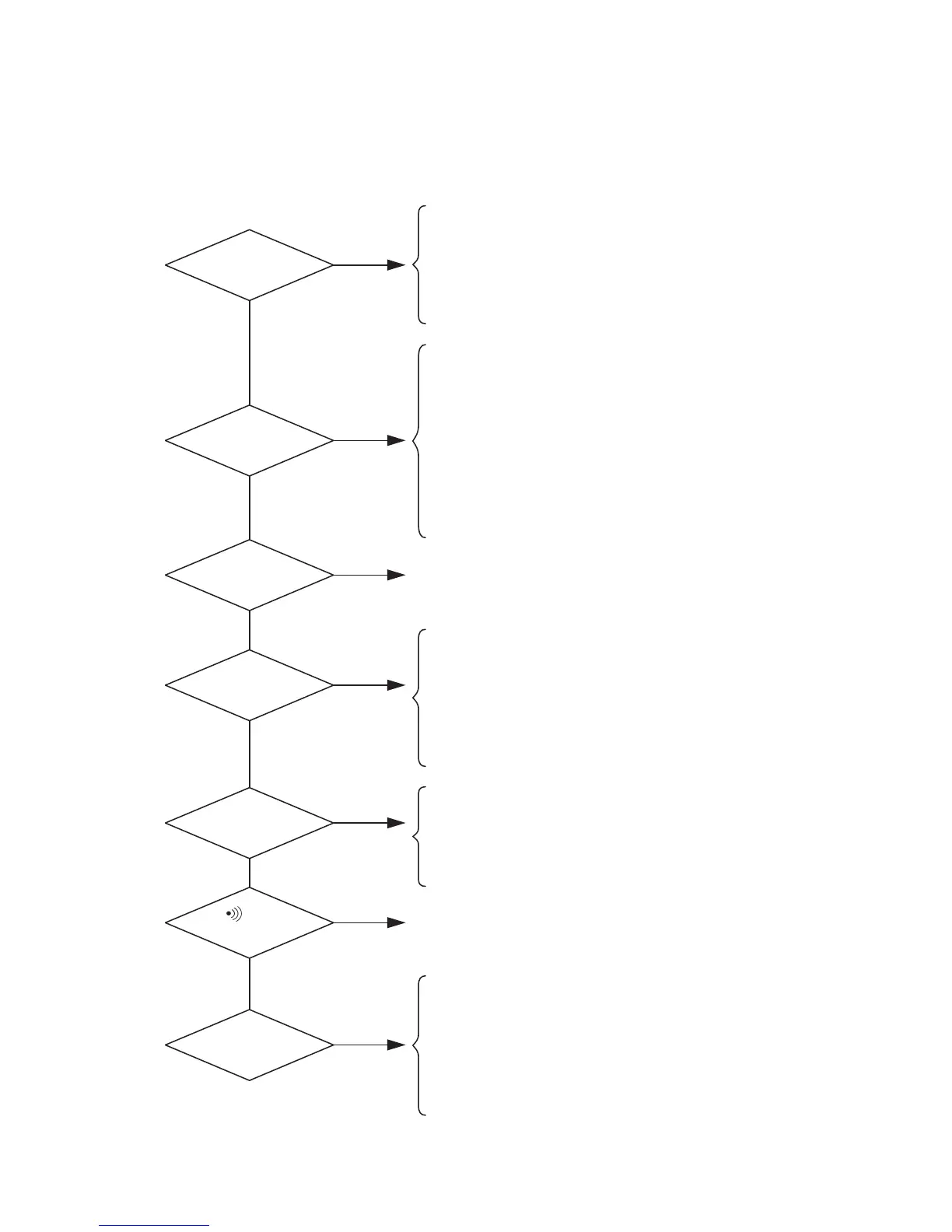
[7] Overview of Troubleshooting
First check that the printed circuit boards are properly snapped into the panel and that the dry cells
are placed in correct polarities.
• The dry cells have run out; the battery terminals were
soldered improperly or in a deformed shape.
• The brush of the Function switch is deformed or missing.
• Quartz oscillator was soldered improperly.
• There is a bridge (short-circuit) due to solder between
pins on the LSI (U1), or the LSI is damaged electrostatically.
• There is a contact failure between the zebra-striped
connector and the printed circuit board.
• The brush of the Function switch is deformed or missing.
• The polarities of the diode (D5) are reversed or there is a
short-circuit between any of its terminals and the pattern
on the printed circuit board due to solder.
• There is a bridge (short-circuit) due to solder between
pins on the LSI (U1), or the LSI is damaged electrostatically.
• The DCV adjustment was not successfully made
because of R3.
• There is wrong wiring for COM or B or improper
soldering.
• The DCV adjustment was not successfully made
because of R3.
• In particular, there is wrong wiring for R19 (PTC), R22,
36, GAP1 or GAP2, improper soldering, or a short-
circuit.
• The resistance value for 26, 28, 29, 30, 32, 33 or 35 is
incorrect or there is a short-circuit.
• In particular, R17, R19 (PTC), R22, 36, GAP1 or GAP2 is
wired improperly, soldered unsuccessfully, or otherwise
short-circuited.
• There is a bridge (short-circuit) between pins on the IC
(U1).
• The buzzer is soldered unsuccessfully or its polarities are
reversed.
• The fuse is blown out, wiring A is soldered unsuccessfully
or involves faulty wiring.
• The polarities of the diode (D5) are reversed or there is a
short-circuit between any of its pins and the circuit board
pattern due to solder.
• R24 is soldered unsuccessfully or its resistance value is
incorrect.
The power does
not turn ON.
The LCD
malfunctions.
There is no
response to any
input.
Voltage cannot be
measured properly.
Resistance cannot be
measured properly.
Current cannot be
measured properly.
The
functional
mode is not available.