15
4. Resistance ( Ω )
For measurements of resistance, a resistor/
voltage conversion (R/V conversion) circuit is
used to convert into DC voltage in proportion to
the resistance value. As a typical example among
several conversion methods available, the method
shown in Fig. 3-9 is explained because it is easily
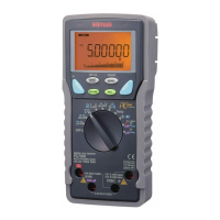
understandable. As shown in Fig. 3-8, accurate
constant current Is is sent to unknown resistor Rx
and then DC voltage is obtained indirectly from
voltage drop V
RX that occurs in proportion to the
resistance value of that resistor. Fig. 3-9 shows an
example of a resistance measuring circuit that
applies the above voltage drop.
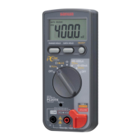
Fig. 3-7: Measuring circuit for DC current (DC µA & mA)
Fig. 3-8:
Principle of resistance measurements
(constant current method)
Fig. 3-9: Resistance ( Ω ) measuring circuit
ES VRX
−
=
−
= IS
RS RX
RS
RX =
−
=
•
VRX
ES
3-5 Working of A/D conversion section
The A/D conversion section converts DC voltage (analog quantity) that has been input from the
input signal conversion section into a pulse number (digital quantity) in proportion to the intensity of
that voltage. The available A/D conversion methods include the integration, comparison, and ∆ ∑
methods. The PC20TK uses the ∆ ∑ method. In this paragraph, however, the double integration
method is explained because it is used for a large number of digital multimeters and theoretically
easier to understand.
1. Operation of each section of double integration circuit
• Integration circuit
This circuit consists of a resistors, a capacitor and an OP amplifier. It outputs a voltage value in
proportion to the product obtained by multiplying the intensity of signal (DC voltage) applied to
the input connector by time (Vo= 1/CR • Vi • T
1).
(Input)
DC current
(DCA)
Electric shunt
Unknown
resistor RX
Constant current Is
Voltage drop
VRX
Readout
A/D
conversion
section
A/D
conversion
section
(Input)
unknown resistor
OP
amplifier
Rx is obtained using
this formula:
Rx =
VRX
Is
Readout